June 23, 2010 |
|
|
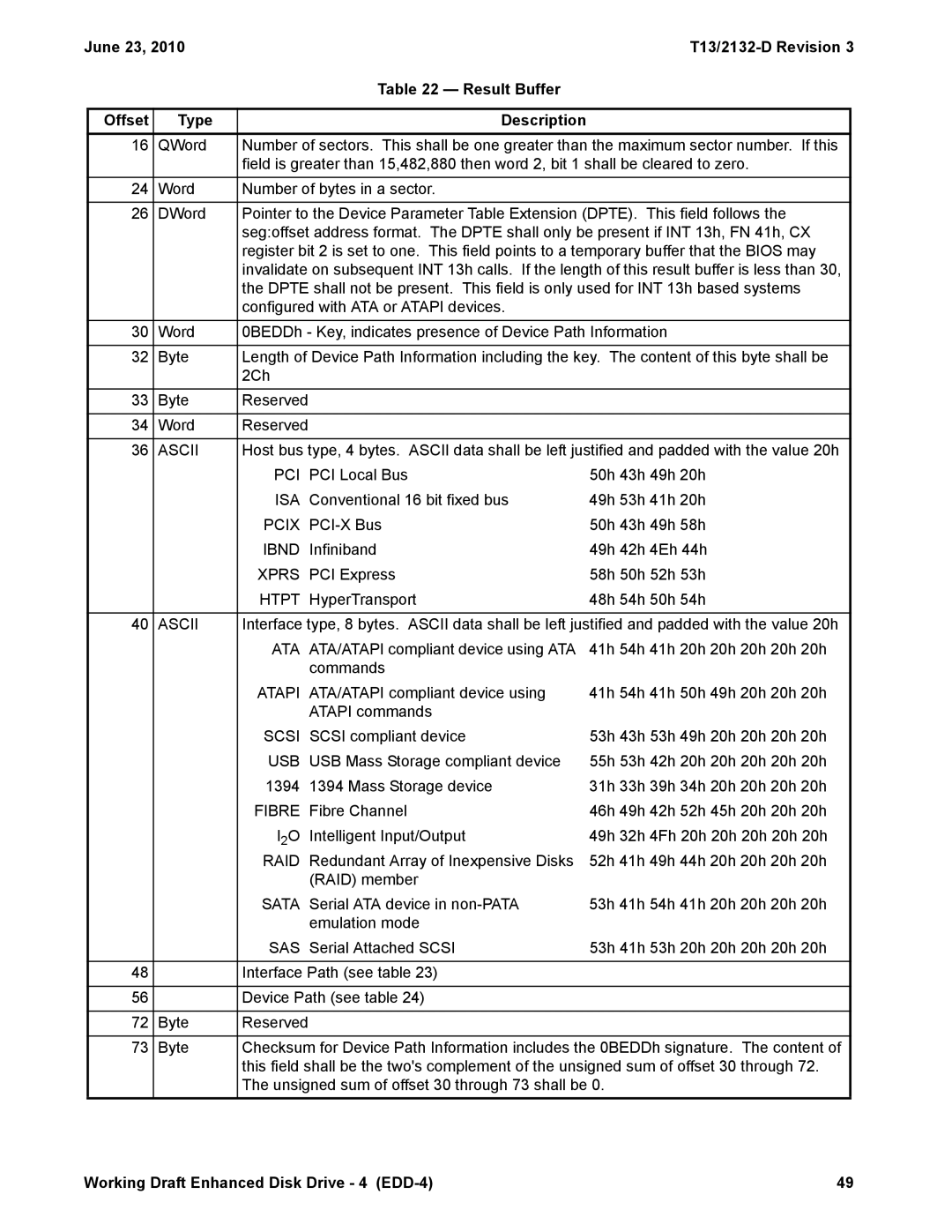
| Table 22 — Result Buffer |
|
|
|
|
|
|
|
|
|
|
Offset | Type |
| Description |
|
|
|
16 | QWord | Number of sectors. This shall be one greater than the maximum sector number. If this | ||||
|
| field is greater than 15,482,880 then word 2, bit 1 shall be cleared to zero. | ||||
|
|
|
|
|
| |
24 | Word | Number of bytes in a sector. |
|
|
| |
|
|
| ||||
26 | DWord | Pointer to the Device Parameter Table Extension (DPTE). This field follows the | ||||
|
| seg:offset address format. The DPTE shall only be present if INT 13h, FN 41h, CX | ||||
|
| register bit 2 is set to one. This field points to a temporary buffer that the BIOS may | ||||
|
| invalidate on subsequent INT 13h calls. If the length of this result buffer is less than 30, | ||||
|
| the DPTE shall not be present. This field is only used for INT 13h based systems | ||||
|
| configured with ATA or ATAPI devices. |
|
|
| |
30 | Word | 0BEDDh - Key, indicates presence of Device Path Information |
| |||
|
|
| ||||
32 | Byte | Length of Device Path Information including the key. The content of this byte shall be | ||||
|
| 2Ch |
|
|
|
|
|
|
|
|
|
|
|
33 | Byte | Reserved |
|
|
|
|
|
|
|
|
|
|
|
34 | Word | Reserved |
|
|
|
|
|
|
| ||||
36 | ASCII | Host bus type, 4 bytes. ASCII data shall be left justified and padded with the value 20h | ||||
|
| PCI | PCI Local Bus | 50h 43h | 49h | 20h |
|
| ISA | Conventional 16 bit fixed bus | 49h 53h | 41h | 20h |
|
| PCIX | 50h 43h | 49h | 58h | |
|
| IBND | Infiniband | 49h 42h | 4Eh 44h | |
|
| XPRS | PCI Express | 58h 50h | 52h | 53h |
|
| HTPT | HyperTransport | 48h 54h | 50h | 54h |
|
|
| ||||
40 | ASCII | Interface type, 8 bytes. ASCII data shall be left justified and padded with the value 20h | ||||
|
| ATA | ATA/ATAPI compliant device using ATA | 41h 54h | 41h | 20h 20h 20h 20h 20h |
|
|
| commands |
|
|
|
|
| ATAPI | ATA/ATAPI compliant device using | 41h 54h | 41h | 50h 49h 20h 20h 20h |
|
|
| ATAPI commands |
|
|
|
|
| SCSI | SCSI compliant device | 53h 43h | 53h | 49h 20h 20h 20h 20h |
|
| USB | USB Mass Storage compliant device | 55h 53h | 42h | 20h 20h 20h 20h 20h |
|
| 1394 | 1394 Mass Storage device | 31h 33h | 39h | 34h 20h 20h 20h 20h |
|
| FIBRE | Fibre Channel | 46h 49h | 42h | 52h 45h 20h 20h 20h |
|
| I2O | Intelligent Input/Output | 49h 32h | 4Fh 20h 20h 20h 20h 20h | |
|
| RAID | Redundant Array of Inexpensive Disks | 52h 41h | 49h | 44h 20h 20h 20h 20h |
|
|
| (RAID) member |
|
|
|
|
| SATA | Serial ATA device in | 53h 41h | 54h | 41h 20h 20h 20h 20h |
|
|
| emulation mode |
|
|
|
|
| SAS | Serial Attached SCSI | 53h 41h | 53h | 20h 20h 20h 20h 20h |
|
|
|
|
|
| |
48 |
| Interface Path (see table 23) |
|
|
| |
|
|
|
|
|
| |
56 |
| Device Path (see table 24) |
|
|
| |
|
|
|
|
|
|
|
72 | Byte | Reserved |
|
|
|
|
|
|
| ||||
73 | Byte | Checksum for Device Path Information includes the 0BEDDh signature. The content of | ||||
|
| this field shall be the two's complement of the unsigned sum of offset 30 through 72. | ||||
|
| The unsigned sum of offset 30 through 73 shall be 0. |
|
| ||
Working Draft Enhanced Disk Drive - 4 | 49 |