| June 23, 2010 | |||
|
|
|
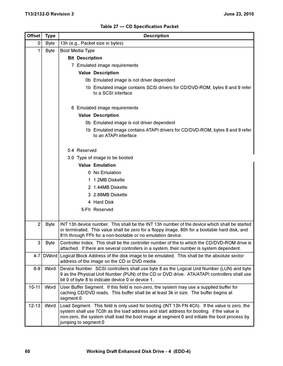
| Table 27 — CD Specification Packet |
|
|
|
|
|
Offset | Type |
|
| Description |
0 | Byte | 13h (e.g., Packet size in bytes) | ||
|
|
| ||
1 | Byte | Boot Media Type | ||
|
| Bit | Description | |
|
| 7 | Emulated image requirements | |
|
|
| Value | Description |
|
|
| 0b | Emulated image is not driver dependent |
|
|
| 1b | Emulated image contains SCSI drivers for |
|
|
|
| to a SCSI interface |
|
| 6 | Emulated image requirements | |
|
|
| Value | Description |
|
|
| 0b | Emulated image is not driver dependent |
|
|
| 1b | Emulated image contains ATAPI drivers for |
|
|
|
| to an ATAPI interface |
|
| 5:4 | Reserved | |
|
| 3:0 | Type of image to be booted | |
|
|
| Value | Emulation |
|
|
| 0 | No Emulation |
|
|
| 1 | 1.2MB Diskette |
|
|
| 2 | 1.44MB Diskette |
|
|
| 3 | 2.88MB Diskette |
|
|
| 4 | Hard Disk |
|
|
| Reserved | |
|
|
| ||
2 | Byte | INT 13h device number. This shall be the INT 13h number of the device which shall be started | ||
|
| or terminated. This value shall be zero for a floppy image, 80h for a bootable hard disk, and | ||
|
| 81h through FFh for a | ||
3 | Byte | Controller Index. This shall be the controller number of the to which the | ||
|
| attached. If there are several controllers in a system, their number is system dependent. | ||
Word | Device Number. SCSI controllers shall use byte 8 as the Logical Unit Number (LUN) and byte | |
|
| 9 as the Physical Unit Number (PUN) of the CD or DVD drive. ATA/ATAPI controllers shall use |
|
| bit 0 of byte 8 to indicate device 0 or device 1. |
Word | User Buffer Segment. If this field is | |
|
| caching CD/DVD reads. This buffer shall be at least 3k in size. The buffer begins at |
|
| segment:0 |
|
|
|
Word | Load Segment. This field is only used for booting (INT 13h FN 4Ch). If the value is zero, the | |
|
| system shall use 7C0h as the load address and start address for booting. if the value is |
|
| |
|
| jumping to segment:0 |
60 | Working Draft Enhanced Disk Drive - 4 |