| June 23, 2010 |
|
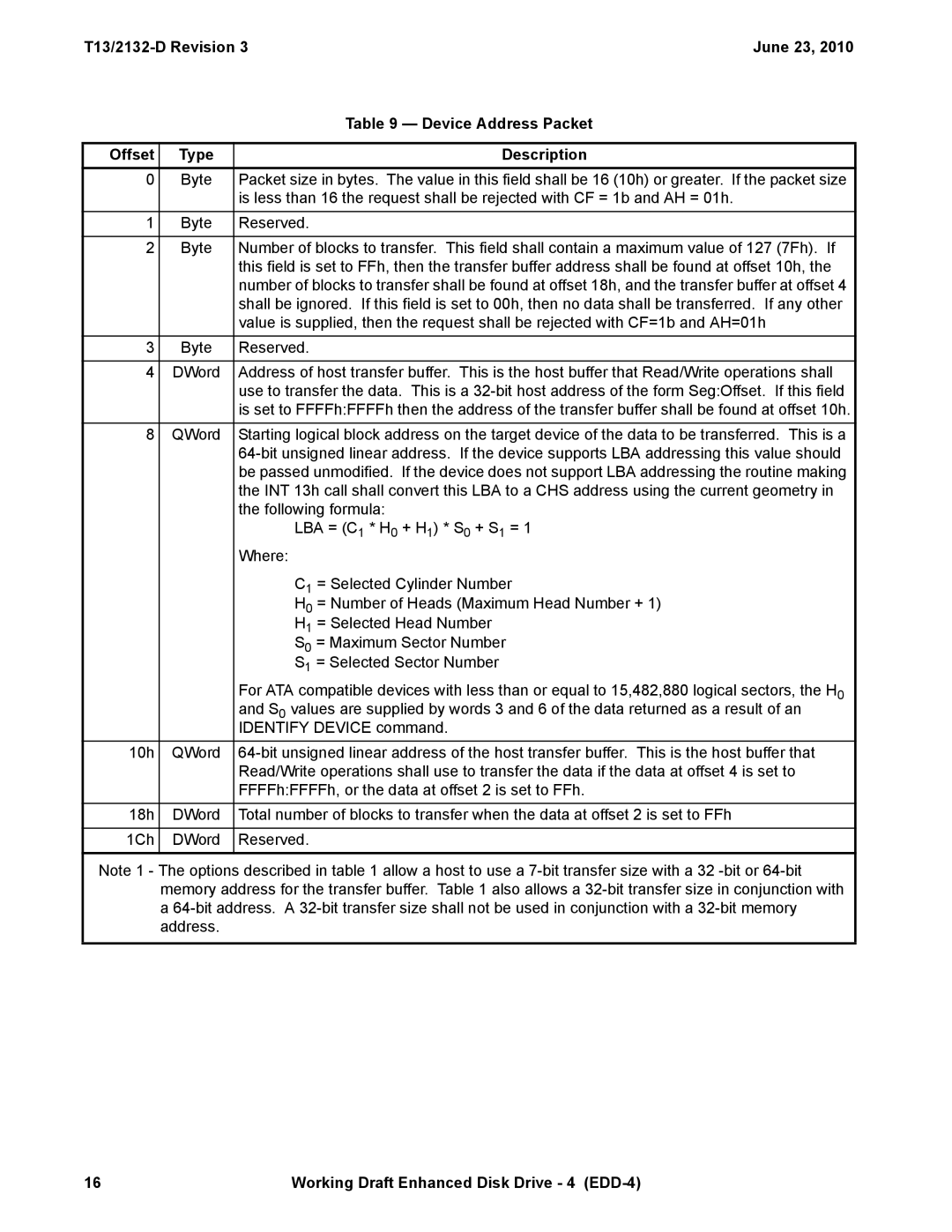
| Table 9 — Device Address Packet |
|
|
|
Offset | Type | Description |
0 | Byte | Packet size in bytes. The value in this field shall be 16 (10h) or greater. If the packet size |
|
| is less than 16 the request shall be rejected with CF = 1b and AH = 01h. |
|
|
|
1 | Byte | Reserved. |
|
|
|
2 | Byte | Number of blocks to transfer. This field shall contain a maximum value of 127 (7Fh). If |
|
| this field is set to FFh, then the transfer buffer address shall be found at offset 10h, the |
|
| number of blocks to transfer shall be found at offset 18h, and the transfer buffer at offset 4 |
|
| shall be ignored. If this field is set to 00h, then no data shall be transferred. If any other |
|
| value is supplied, then the request shall be rejected with CF=1b and AH=01h |
|
|
|
3 | Byte | Reserved. |
|
|
|
4 | DWord | Address of host transfer buffer. This is the host buffer that Read/Write operations shall |
|
| use to transfer the data. This is a |
|
| is set to FFFFh:FFFFh then the address of the transfer buffer shall be found at offset 10h. |
8 | QWord | Starting logical block address on the target device of the data to be transferred. This is a |
|
| |
|
| be passed unmodified. If the device does not support LBA addressing the routine making |
|
| the INT 13h call shall convert this LBA to a CHS address using the current geometry in |
|
| the following formula: |
|
| LBA = (C1 * H0 + H1) * S0 + S1 = 1 |
|
| Where: |
|
| C1 = Selected Cylinder Number |
|
| H0 = Number of Heads (Maximum Head Number + 1) |
|
| H1 = Selected Head Number |
|
| S0 = Maximum Sector Number |
|
| S1 = Selected Sector Number |
|
| For ATA compatible devices with less than or equal to 15,482,880 logical sectors, the H0 |
|
| and S0 values are supplied by words 3 and 6 of the data returned as a result of an |
|
| IDENTIFY DEVICE command. |
10h | QWord | |
|
| Read/Write operations shall use to transfer the data if the data at offset 4 is set to |
|
| FFFFh:FFFFh, or the data at offset 2 is set to FFh. |
18h | DWord | Total number of blocks to transfer when the data at offset 2 is set to FFh |
|
|
|
1Ch | DWord | Reserved. |
|
|
|
Note 1 - The options described in table 1 allow a host to use a
16 | Working Draft Enhanced Disk Drive - 4 |