| June 23, 2010 |
4 Overview
In the past, DOS has accessed its mass storage devices using a BIOS provided INT 13h interface. This interface was designed in the early 1980's and upgraded in the late 1980's. The maximum capacity that can be addressed by this Applications Program Interface (API) on a disk drive is 8.4 GB. The INT 13h interface, now known as the conventional INT 13h interface, uses function numbers 01h through 3Fh and is
a)Replace CHS addressing with Logical Block Addressing (LBA);
b)Remove the current requirement of using interrupt 41h/46h to point at the Fixed Disk Parameter Table information (see 8.20.4);
c)Make location and configuration information available to operating systems that do not use the BIOS to access mass storage devices;
d)Use data structures that apply to both
e)Use data structures that can address media capacities for the next 20 years.
Many BIOS, Option ROM, and OS vendors have already implemented the functions defined in this document for ATA and SCSI style devices. This standard builds on
DOS and other operating systems, such as Windows® 98, Windows® NT, Windows® 2000, and Windows® XP, add the capability to consistently provide the same drive letter assignments to the user. The result of this capability is that storage devices can be added to an EDD system, and the existing drive letters do not change.
Data written on media can render the media incompatible with certain drive letters when some drive letter based operating systems are used. Technologies, such as IEEE
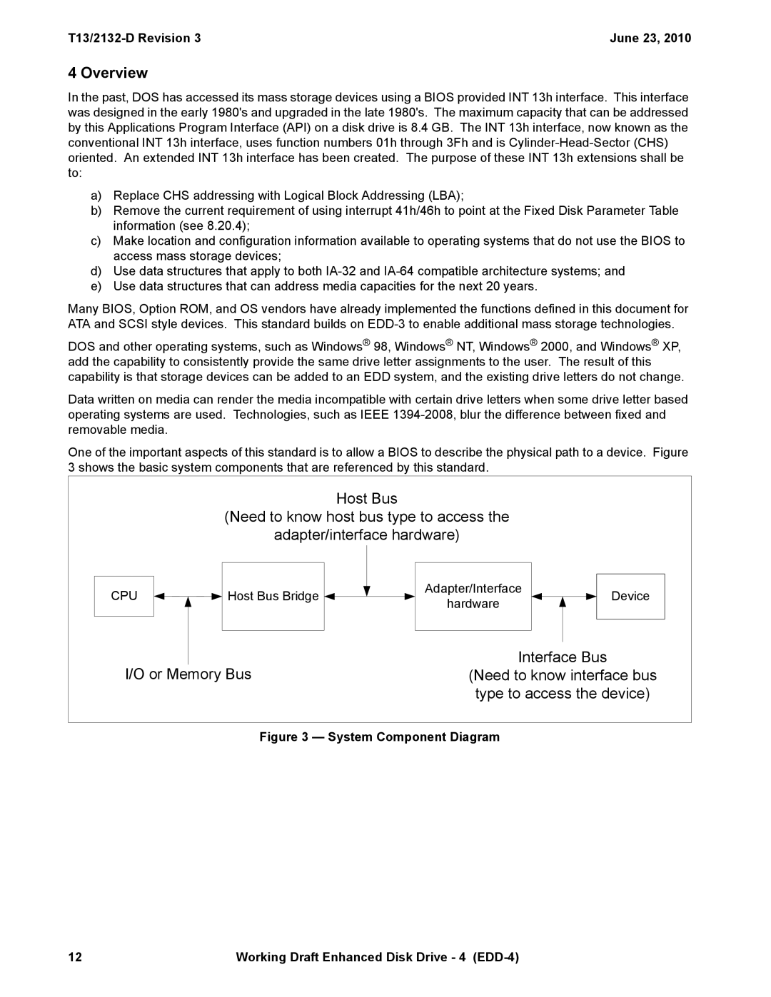
One of the important aspects of this standard is to allow a BIOS to describe the physical path to a device. Figure 3 shows the basic system components that are referenced by this standard.
Host Bus
(Need to know host bus type to access the
adapter/interface hardware)
|
|
|
|
|
|
|
|
|
|
|
|
|
|
| Adapter/Interface |
CPU |
| Host Bus Bridge |
|
|
|
| |
|
|
|
|
| |||
|
|
|
|
| hardware | ||
|
|
|
|
|
|
| |
|
|
|
|
|
|
|
|
|
|
|
|
|
|
|
|
Device
Interface Bus
I/O or Memory Bus(Need to know interface bus type to access the device)
Figure 3 — System Component Diagram
12 | Working Draft Enhanced Disk Drive - 4 |