June 23, 2010 |
This PSS shall add transport specific information (e.g., header information and CRC) and modify the CDB where necessary with bus specific information. If the secondary bus is a
8.27.2.2 Formatted Protocol Specific Data
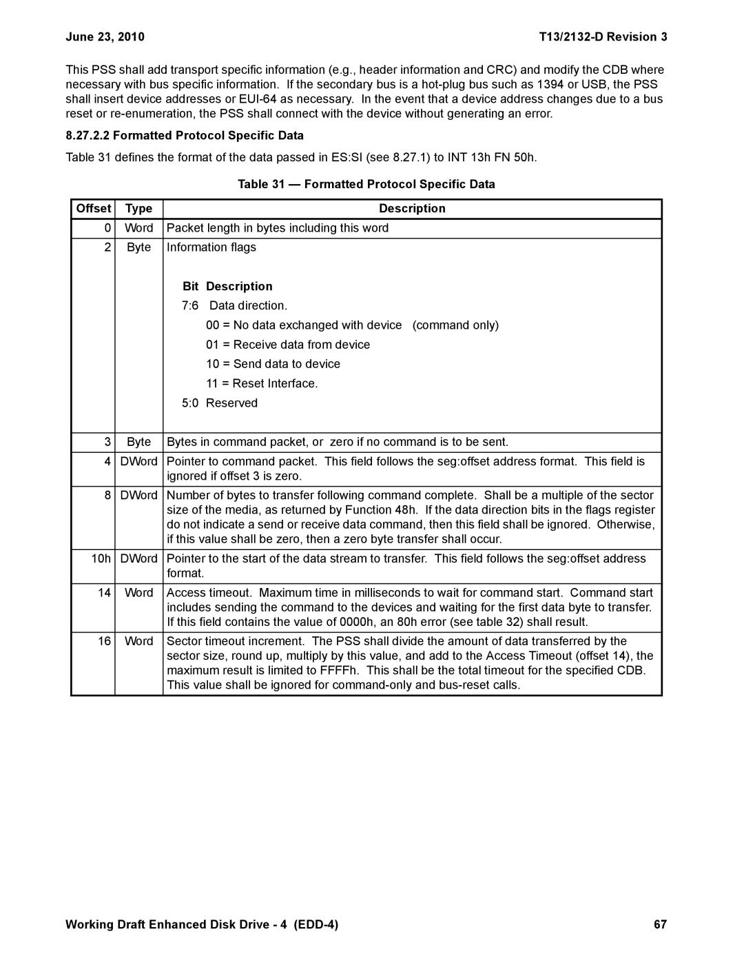
Table 31 defines the format of the data passed in ES:SI (see 8.27.1) to INT 13h FN 50h.
|
|
| Table 31 — Formatted Protocol Specific Data |
|
|
|
|
Offset | Type |
| Description |
0 | Word | Packet length in bytes including this word | |
|
|
| |
2 | Byte | Information flags | |
|
| Bit | Description |
|
| 7:6 | Data direction. |
|
|
| 00 = No data exchanged with device (command only) |
|
|
| 01 = Receive data from device |
|
|
| 10 = Send data to device |
|
|
| 11 = Reset Interface. |
|
| 5:0 | Reserved |
|
|
| |
3 | Byte | Bytes in command packet, or zero if no command is to be sent. | |
|
|
| |
4 | DWord | Pointer to command packet. This field follows the seg:offset address format. This field is | |
|
| ignored if offset 3 is zero. | |
|
|
| |
8 | DWord | Number of bytes to transfer following command complete. Shall be a multiple of the sector | |
|
| size of the media, as returned by Function 48h. If the data direction bits in the flags register | |
|
| do not indicate a send or receive data command, then this field shall be ignored. Otherwise, | |
|
| if this value shall be zero, then a zero byte transfer shall occur. | |
10h | DWord | Pointer to the start of the data stream to transfer. This field follows the seg:offset address | |
|
| format. |
|
|
|
| |
14 | Word | Access timeout. Maximum time in milliseconds to wait for command start. Command start | |
|
| includes sending the command to the devices and waiting for the first data byte to transfer. | |
|
| If this field contains the value of 0000h, an 80h error (see table 32) shall result. | |
|
|
| |
16 | Word | Sector timeout increment. The PSS shall divide the amount of data transferred by the | |
|
| sector size, round up, multiply by this value, and add to the Access Timeout (offset 14), the | |
|
| maximum result is limited to FFFFh. This shall be the total timeout for the specified CDB. | |
|
| This value shall be ignored for | |
Working Draft Enhanced Disk Drive - 4 | 67 |
