IPS-800CE-D16 & IPS-1600CE-D16 - User’s Guide
IPS UNIT
POWER INLETS
BOTTOM
PLATE
SLIDER
SCREW PLATE RECEPTACLES
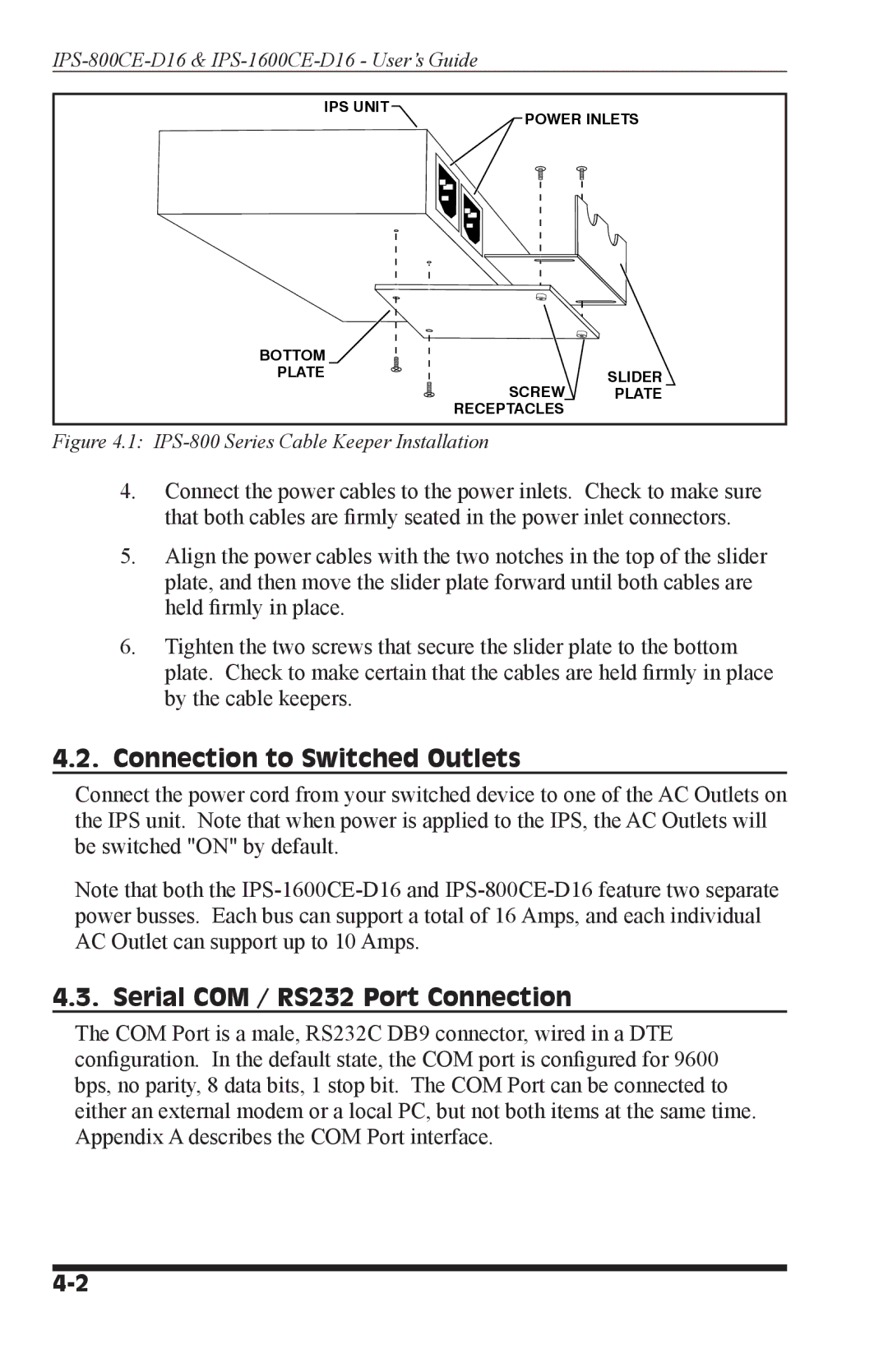
Figure 4.1: IPS-800 Series Cable Keeper Installation
4.Connect the power cables to the power inlets. Check to make sure that both cables are firmly seated in the power inlet connectors.
5.Align the power cables with the two notches in the top of the slider plate, and then move the slider plate forward until both cables are held firmly in place.
6.Tighten the two screws that secure the slider plate to the bottom plate. Check to make certain that the cables are held firmly in place by the cable keepers.
4.2.Connection to Switched Outlets
Connect the power cord from your switched device to one of the AC Outlets on the IPS unit. Note that when power is applied to the IPS, the AC Outlets will be switched "ON" by default.
Note that both the
4.3. Serial COM / RS232 Port Connection
The COM Port is a male, RS232C DB9 connector, wired in a DTE configuration. In the default state, the COM port is configured for 9600 bps, no parity, 8 data bits, 1 stop bit. The COM Port can be connected to either an external modem or a local PC, but not both items at the same time. Appendix A describes the COM Port interface.