2. Unit Description
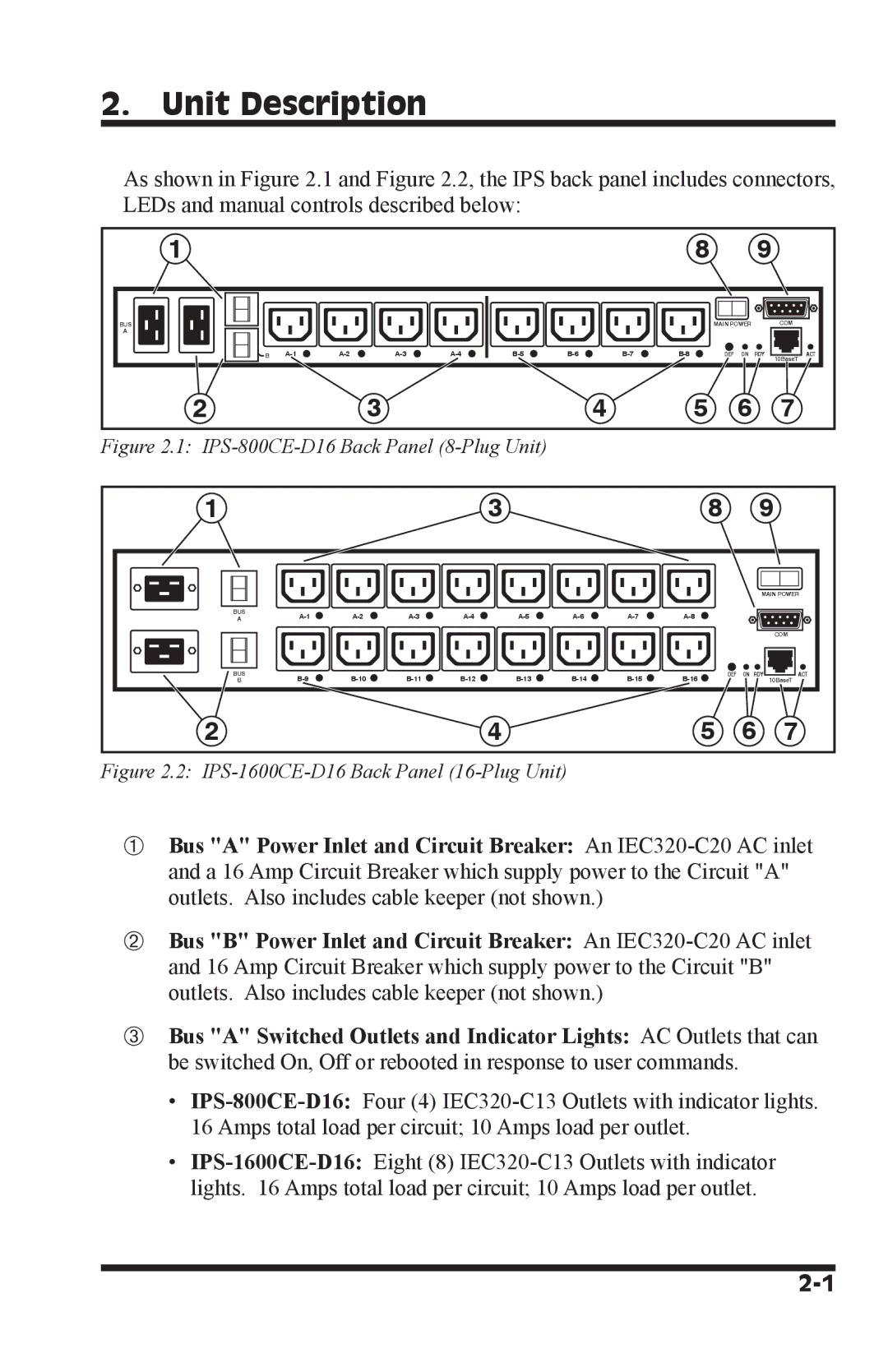
As shown in Figure 2.1 and Figure 2.2, the IPS back panel includes connectors, LEDs and manual controls described below:
1 | 8 | 9 |
BUS
A
B |
|
|
|
| MAIN POWER | COM |
|
DEF ON RDY | 10BaseT | ACT | ||||
|
|
|
|
|
|
2 | 3 | 4 | 5 | 6 | 7 |
Figure 2.1: IPS-800CE-D16 Back Panel (8-Plug Unit)
1 |
|
|
|
| 3 |
|
|
| 8 | 9 | |
|
|
|
|
|
|
|
|
|
| MAIN POWER | |
BUS |
|
|
| ||||||||
A |
|
|
| ||||||||
|
|
|
|
|
|
|
|
|
|
| COM |
BUS | DEF | ON RDY | ACT | ||||||||
B |
|
| 10BaseT | ||||||||
2 |
|
|
|
| 4 |
|
|
| 5 | 6 | 7 |
Figure 2.2: IPS-1600CE-D16 Back Panel (16-Plug Unit)
➀Bus "A" Power Inlet and Circuit Breaker: An
➁Bus "B" Power Inlet and Circuit Breaker: An
➂Bus "A" Switched Outlets and Indicator Lights: AC Outlets that can be switched On, Off or rebooted in response to user commands.
•
•