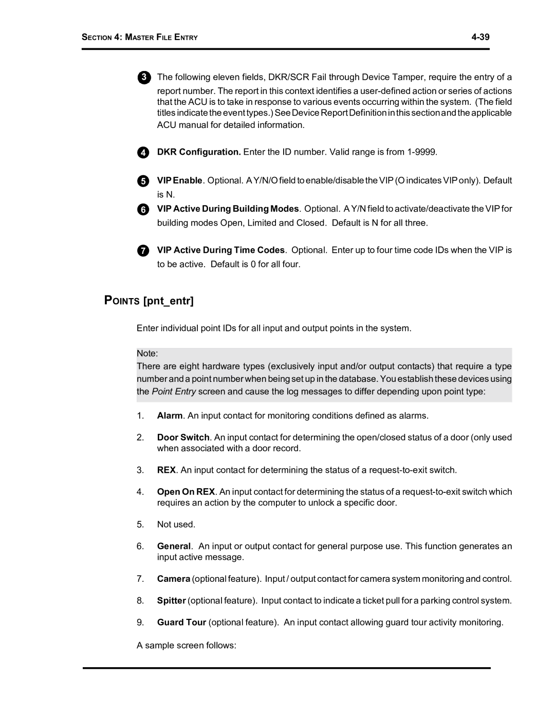
SE 6000 specifications
The Westinghouse SE 6000 is an advanced digital power management system designed for comprehensive control over electrical grids and power generation facilities. Its versatility and reliability make it a favored choice among utility providers and energy managers. The SE 6000 is equipped with numerous features that enhance efficiency, safety, and operational oversight.One of the standout features of the Westinghouse SE 6000 is its robust data analytics capability. The system employs state-of-the-art telemetry and monitoring technologies that allow for real-time data collection and analysis. This enables operators to track power usage trends, identify inefficiencies, and make informed decisions regarding energy distribution and consumption.
Another key characteristic of the SE 6000 is its support for multiple communication protocols. This compatibility ensures seamless integration with existing infrastructure and facilitates interoperability among various devices and systems. Whether using DNP3, IEC 61850, or other industry-standard protocols, users can easily connect the SE 6000 to their grid management systems.
The SE 6000 features advanced protection mechanisms that are crucial for maintaining system integrity. Its built-in protection algorithms monitor for fault conditions and automatically execute pre-configured responses, thereby minimizing downtime and ensuring uninterrupted power delivery. This proactive approach to fault management helps safeguard both equipment and personnel.
In terms of user experience, the SE 6000 boasts an intuitive interface that simplifies the complexity of power management. The graphical user interface is designed with operator ergonomics in mind, offering customizable dashboards and clear visualizations of system performance metrics. This makes it easier for operators to monitor operations and respond quickly to potential issues.
Moreover, the SE 6000 is designed to support renewable energy systems, showcasing its adaptability to the evolving energy landscape. With the increasing integration of solar, wind, and other renewable sources, this platform is geared toward facilitating grid stability and reliability in conjunction with fluctuating power outputs.
Overall, the Westinghouse SE 6000 represents a modern solution in the realm of power management systems. By leveraging cutting-edge technologies, it provides utilities with the tools necessary to enhance operational efficiency, increase safety, and embrace the transition toward sustainable energy practices. Its combination of robust features, user-friendly design, and adaptability makes it a leading choice in power system management.

