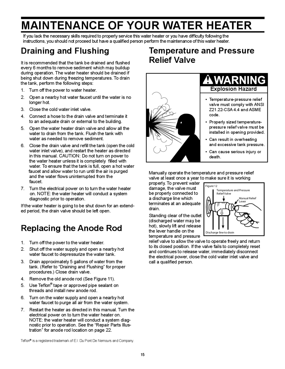
Figure 12
Temperature and Pressure Relief Valve
Manual Relief
Lever
Discharge line to drain

MAINTENANCE OF YOUR WATER HEATER

If you lack the necessary skills required to properly service this water heater or you have difficulty following the instructions, you should not proceed but have a qualified person perform the maintenance of this water heater.

Draining and Flushing

It is recommended that the tank be drained and flushed every 6 months to remove sediment which may buildup during operation. The water heater should be drained if being shut down during freezing temperatures. To drain the tank, perform the following steps:

1.Turn off the power to water heater.

2.Open a nearby hot water faucet until the water is no longer hot.

3.Close the cold water inlet valve.

4.Connect a hose to the drain valve and terminate it to an adequate drain or external to the building.

5.Open the water heater drain valve and allow all the water to drain from the tank. Flush the tank with water as needed to remove sediment.

6.Close the drain valve and refill the tank (open the cold water inlet valve), and restart the heater as directed in this manual. CAUTION: Do not turn on power to the water heater unless it is completely filled with water. To ensure that the tank is full, open a hot water faucet and allow water to run until the air is purged and the water flows uninterrupted from the

faucet.

7.Turn the electrical power on to turn the water heater on. NOTE: the water heater will conduct a system diagnostic prior to operation.

If the water heater is going to be shut down for an extend- ed period, the drain valve should be left open.

Replacing the Anode Rod

1.Turn off the power to the water heater.

2.Shut off the water supply and open a nearby hot water faucet to depressurize the water tank.

3.Drain approximately 5 gallons of water from the tank. (Refer to “Draining and Flushing” for proper procedures.) Close drain valve.

4.Remove the old anode rod (See Figure 11).

5.Use Teflon® tape or approved pipe sealant on threads and install new anode rod.

6.Turn on the water supply and open a nearby hot water faucet to purge all air from the water system.

7.Restart the heater as directed in this manual. Turn the electrical power on to turn the water heater on. NOTE: the water heater will conduct a system diag- nostic prior to operation. See the “Repair Parts Illus- tration” for anode rod location on page 22.

Teflon® is a registered trademark of E.I. Du Pont De Nemours and Company.

Temperature and Pressure Relief Valve

Explosion Hazard

Temperature-pressure relief valve must comply with ANSI Z21.22-CSA 4.4 and ASME code.

• Properly sized temperature- pressure relief valve must be installed in opening provided.

• Can result in overheating and excessive tank pressure.

• Can cause serious injury or death.

Manually operate the temperature and pressure relief valve at least once a year to make sure it is working properly. To prevent water

damage, the valve must be properly connected to a discharge line which

terminates at an adequate drain.

Standing clear of the outlet (discharged water may be hot), slowly lift and release the lever handle on the

temperature and pressure

relief valve to allow the valve to operate freely and return to its closed position. If the valve fails to completely reset and continues to release water, immediately disconnect the electrical power, close the cold water inlet valve and call a qualified person.

15

Page 15
Image 15
Whirlpool 318686-000 Maintenance of Your Water Heater, Draining and Flushing, Replacing the Anode Rod

318686-000 specifications

The Whirlpool 318686-000 is a highly regarded appliance part that plays an essential role in modern kitchen functionality. Designed with the user in mind, it boasts several features and technologies that enhance its performance and reliability.

One of the primary characteristics of the Whirlpool 318686-000 is its compatibility with a wide range of Whirlpool ovens and ranges, making it a versatile choice for many households. This part is commonly known as the surface element, which provides the necessary heat for cooking a variety of dishes. Its design ensures even heat distribution, which is vital for achieving perfectly cooked meals every time.

The Whirlpool 318686-000 is engineered with durability in mind. Constructed from high-quality materials, this part is built to withstand the daily stresses of cooking while maintaining its performance. This longevity translates into reduced replacement costs and increased satisfaction for users, making it an economical choice for homeowners.

In terms of safety, the Whirlpool 318686-000 features advanced technology to minimize risks associated with cooking. It typically includes integrated thermal protection, which helps prevent overheating. This feature not only prolongs the lifespan of the component but also ensures a safer cooking environment for users.

Installation of the Whirlpool 318686-000 is designed to be user-friendly. Homeowners can replace this part without needing specialized tools or professional assistance, allowing for convenient maintenance. This ease of installation is especially appealing for those who prefer a DIY approach to home repairs.

Efficiency is another hallmark of the Whirlpool 318686-000. The design optimizes energy consumption, allowing users to cook efficiently while saving on utility costs. The element heats up quickly, reducing wait times and enhancing overall cooking experiences.

Whirlpool is a brand synonymous with innovation, and the 318686-000 reflects this commitment to excellence. The part combines modern technology with practical design, ensuring it meets the needs of contemporary cooking. With its blend of durability, safety, efficiency, and ease of use, the Whirlpool 318686-000 is an essential addition to any kitchen, providing reliable performance that cooks can depend on for years to come. Whether replacing a worn-out part or upgrading to enhance cooking capabilities, this surface element is a top choice for Whirlpool appliance users.