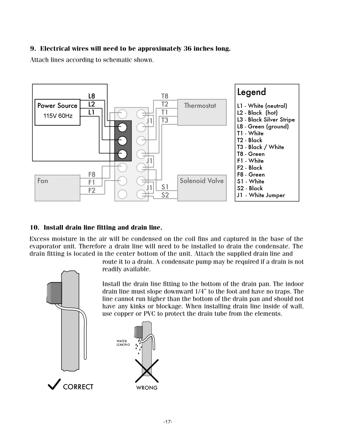
9.Electrical wires will need to be approximately 36 inches long. Attach lines according to schematic shown.
|
|
| L8 |
|
|
|
|
|
|
|
| Power Source | L2 |
|
|
|
|
|
|
| |
| 115V 60Hz |
| L1 |
|
|
|
|
|
|
|
|
|
|
|
|
|
|
|
| ||
|
|
|
|
|
|
|
|
|
| |
|
|
|
|
|
|
|
|
|
|
|
|
|
|
|
|
|
|
|
|
|
|
|
|
|
|
|
|
|
|
|
|
|
|
|
|
|
|
|
|
|
|
|
|
|
|
|
|
|
|
|
|
|
|
|
|
|
|
|
|
|
|
|
|
|
|
F8
FanF1
F2
T8
T2
T1
J1 T3
J1
J1 S1 

 S2
S2
Thermostat
Solenoid Valve
Legend
L1 - White (neutral)
L2 - Black (hot)
L3 - Black Silver Stripe
L8 - Green (ground)
T1 - White
T2 - Black
T3 - Black / White
T8 - Green
F1 - White
F2 - Black
F8 - Green
S1 - White
S2 - Black
J1 - White Jumper
10. Install drain line fitting and drain line.
Excess moisture in the air will be condensed on the coil fins and captured in the base of the evaporator unit. Therefore a drain line will need to be installed to drain the condensate. The drain fitting is located in the center bottom of the unit. Attach the supplied drain line and
route it to a drain. A condensate pump may be required if a drain is not readily available.
Install the drain line fitting to the bottom of the drain pan. The indoor drain line must slope downward 1/4” to the foot and have no traps. The line cannot run higher than the bottom of the drain pan and should not have any kinks or blockage. When installing drain line inside of wall, use copper or PVC to protect the drain tube from the elements.
WATER
LEAKING
![]() CORRECT WRONG
CORRECT WRONG
