5 minutes between cooling cycles. The following may cause a time delay in COOL:
a) Return of power after a power outage.
b) Pressing | SYSTEM | to change operating |
SWITCH | ||
modes. |
|
|
c)Pressing ![]() or
or ![]() , creating a call for COOL too soon after a previous call.
, creating a call for COOL too soon after a previous call.
•SYSTEM INDICATOR LIGHTS — The red indicator light comes on whenever the heat- ing or cooling system is operating. The yellow indicator light comes on when the second stage of heating or cooling is oper- ating.
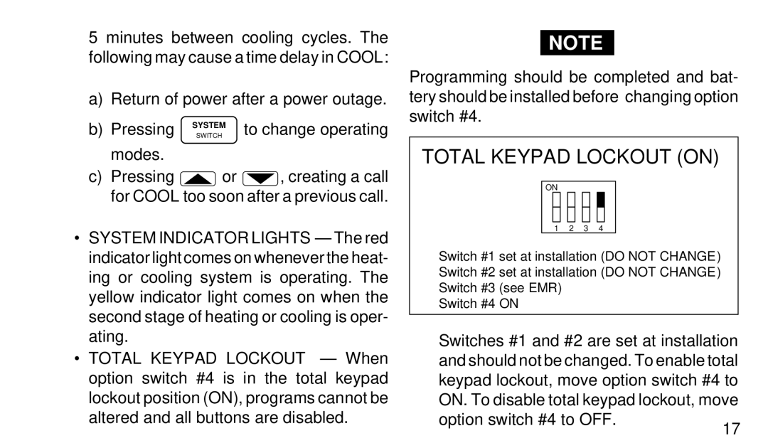
•TOTAL KEYPAD LOCKOUT — When option switch #4 is in the total keypad lockout position (ON), programs cannot be altered and all buttons are disabled.
NOTE
Programming should be completed and bat- tery should be installed before changing option switch #4.
TOTAL KEYPAD LOCKOUT (ON)
ON
1 2 3 4
Switch #1 set at installation (DO NOT CHANGE) Switch #2 set at installation (DO NOT CHANGE) Switch #3 (see EMR)
Switch #4 ON
Switches #1 and #2 are set at installation and should not be changed. To enable total keypad lockout, move option switch #4 to ON. To disable total keypad lockout, move
option switch #4 to OFF.
17
