BB720X, BB840XP, BB840X, BB600X specifications
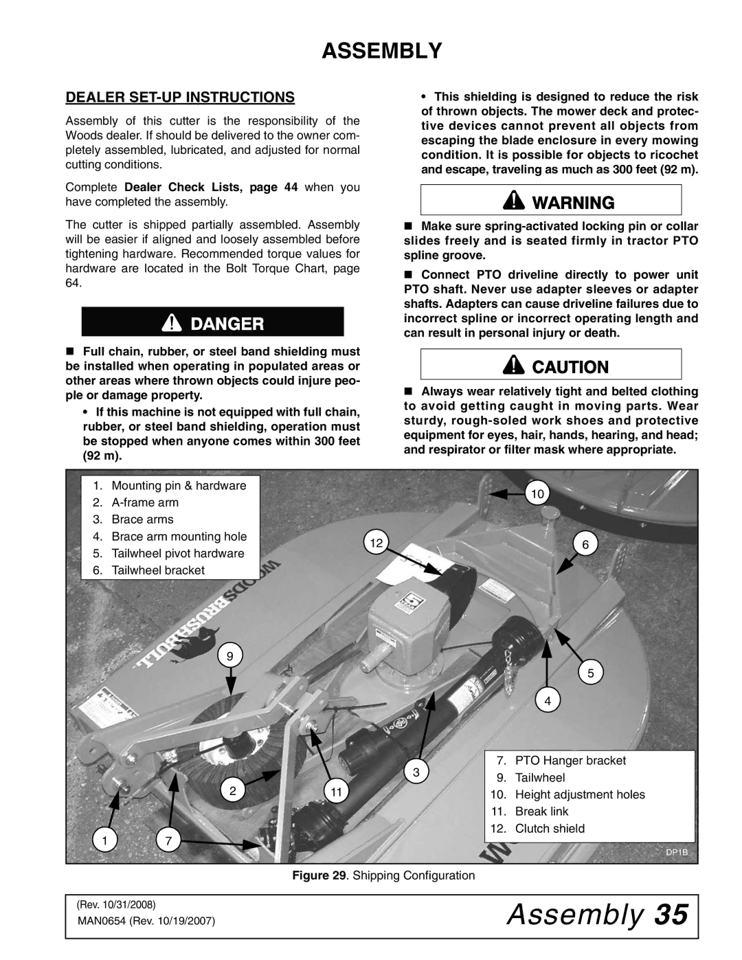
Woods Equipment has established itself as a leader in the manufacturing of high-quality agricultural implements, particularly in the realm of rotary cutters. Among their standout products are the BB840X, BB600X, BB840XP, and BB720X models, which offer versatility, durability, and efficiency for land management and maintenance.The BB840X is an exceptional rotary cutter designed for heavy-duty applications. It features a robust frame and a powerful cutting deck that allows it to tackle tough brush and dense vegetation with ease. Its innovative design includes a reinforced gearbox and unique blade configuration, ensuring maximum cutting performance. Moreover, the BB840X is equipped with an adjustable cutting height, which enhances its adaptability on various terrains.
Similarly, the BB600X offers a smaller footprint while still delivering impressive cutting capabilities. This model is particularly suited for smaller tractors and lighter-duty applications. The BB600X incorporates a rugged design that facilitates easy maneuverability, making it an ideal choice for homeowners and professional landscapers alike who are looking to maintain their properties effectively. Its efficient blade design not only provides clean cuts but also reduces maintenance time.
The BB840XP represents the next level in rotary cutting technology with its enhanced performance features. This model showcases Woods' commitment to innovation by integrating advanced technologies that improve efficiency and reduce wear and tear. The BB840XP includes a patented cutting system that allows for a smoother cutting experience, even in challenging environments. Additionally, it features superior blade support, ensuring longevity and reducing the need for frequent replacements.
Lastly, the BB720X rounds out this lineup, tailored for those seeking a balance between performance and portability. The BB720X is lightweight yet sturdy, making it suitable for a range of tasks, from mowing fields to clearing trails. Its compact design allows it to fit into tighter spaces without compromising on performance. The BB720X also boasts user-friendly adjustments, enabling operators to change cutting settings seamlessly.
All four models come equipped with Woods' durable construction and are backed by a comprehensive warranty, reflecting the company's commitment to quality. Whether for agricultural use, landscaping, or maintaining personal properties, the Woods Equipment BB840X, BB600X, BB840XP, and BB720X provide dependable solutions that enhance productivity and ensure excellent results in any cutting application.

