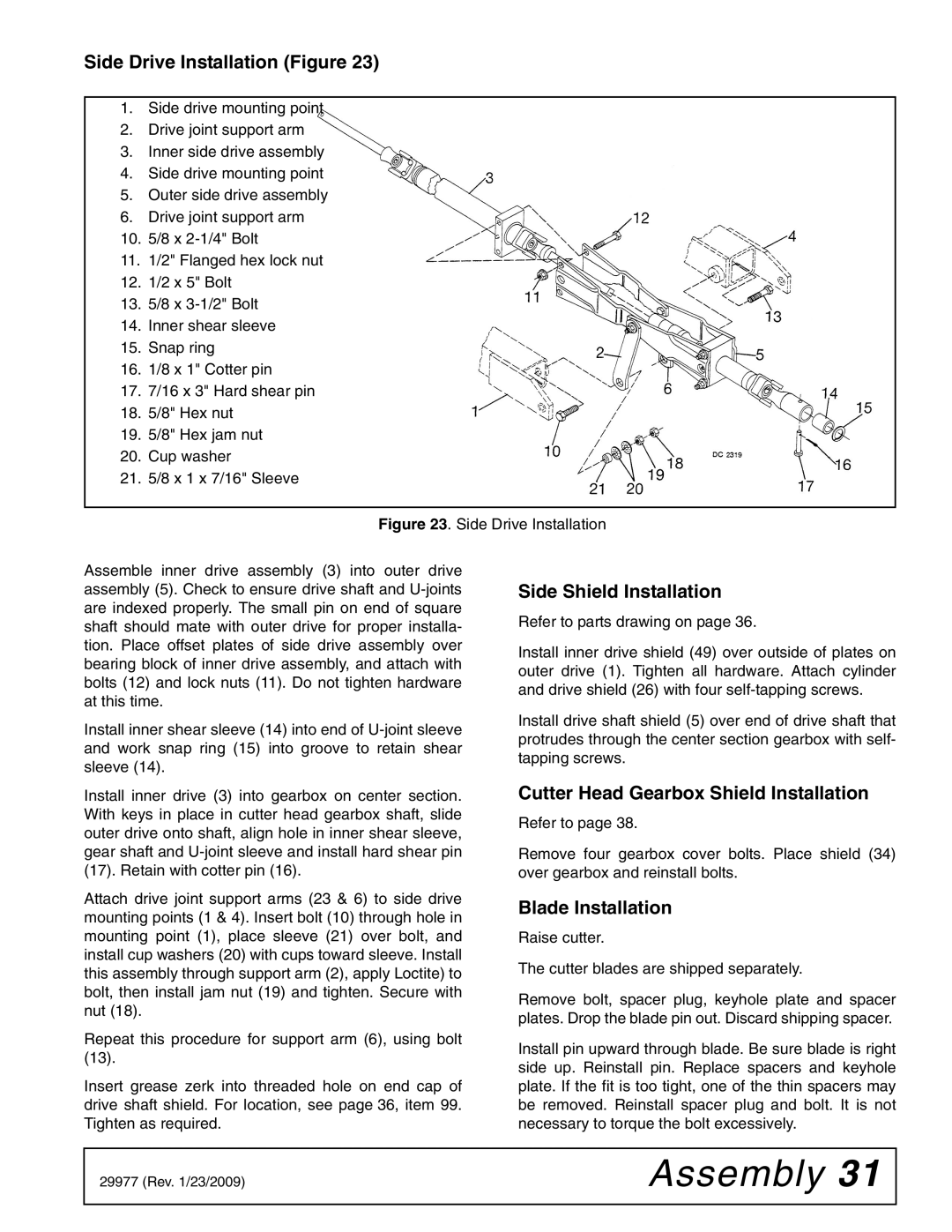
Side Drive Installation (Figure 23)
1.Side drive mounting point
2.Drive joint support arm
3.Inner side drive assembly
4.Side drive mounting point
5.Outer side drive assembly
6.Drive joint support arm
10.5/8 x
11.1/2" Flanged hex lock nut
12.1/2 x 5" Bolt
13.5/8 x
14.Inner shear sleeve
15.Snap ring
16.1/8 x 1" Cotter pin
17.7/16 x 3" Hard shear pin
18.5/8" Hex nut
19.5/8" Hex jam nut
20.Cup washer
21.5/8 x 1 x 7/16" Sleeve
Figure 23. Side Drive Installation
Assemble inner drive assembly (3) into outer drive assembly (5). Check to ensure drive shaft and U-joints are indexed properly. The small pin on end of square shaft should mate with outer drive for proper installa- tion. Place offset plates of side drive assembly over bearing block of inner drive assembly, and attach with bolts (12) and lock nuts (11). Do not tighten hardware at this time.
Install inner shear sleeve (14) into end of U-joint sleeve and work snap ring (15) into groove to retain shear sleeve (14).
Install inner drive (3) into gearbox on center section. With keys in place in cutter head gearbox shaft, slide outer drive onto shaft, align hole in inner shear sleeve, gear shaft and U-joint sleeve and install hard shear pin (17). Retain with cotter pin (16).
Attach drive joint support arms (23 & 6) to side drive mounting points (1 & 4). Insert bolt (10) through hole in mounting point (1), place sleeve (21) over bolt, and install cup washers (20) with cups toward sleeve. Install this assembly through support arm (2), apply Loctite) to bolt, then install jam nut (19) and tighten. Secure with nut (18).
Repeat this procedure for support arm (6), using bolt (13).
Insert grease zerk into threaded hole on end cap of drive shaft shield. For location, see page 36, item 99. Tighten as required.
Side Shield Installation
Refer to parts drawing on page 36.
Install inner drive shield (49) over outside of plates on outer drive (1). Tighten all hardware. Attach cylinder and drive shield (26) with four
Install drive shaft shield (5) over end of drive shaft that protrudes through the center section gearbox with self- tapping screws.
Cutter Head Gearbox Shield Installation
Refer to page 38.
Remove four gearbox cover bolts. Place shield (34) over gearbox and reinstall bolts.
Blade Installation
Raise cutter.
The cutter blades are shipped separately.
Remove bolt, spacer plug, keyhole plate and spacer plates. Drop the blade pin out. Discard shipping spacer.
Install pin upward through blade. Be sure blade is right side up. Reinstall pin. Replace spacers and keyhole plate. If the fit is too tight, one of the thin spacers may be removed. Reinstall spacer plug and bolt. It is not necessary to torque the bolt excessively.
29977 (Rev. 1/23/2009) | Assembly 31 |
|
|