M1001 6" x 26" Vertical Mill
Assembly
SET UP
The Model M1001 comes fully assembled from the factory with the exception of one of the longitudinal handwheels and the cross handwheel. The head has been rotated to reduce the overall dimension of the shipping crate.
Headstock Adjustment
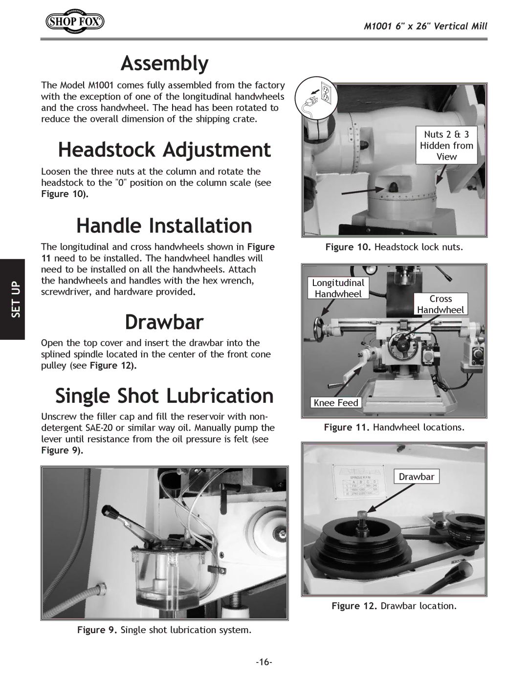
Loosen the three nuts at the column and rotate the headstock to the "0" position on the column scale (see
Figure 10).
Handle Installation
The longitudinal and cross handwheels shown in Figure 11 need to be installed. The handwheel handles will need to be installed on all the handwheels. Attach the handwheels and handles with the hex wrench, screwdriver, and hardware provided.
Drawbar
Open the top cover and insert the drawbar into the splined spindle located in the center of the front cone pulley (see Figure 12).
Single Shot Lubrication
Unscrew the filler cap and fill the reservoir with non- detergent
Figure 9).
Nuts 2 & 3
Hidden from
View
Figure 10. Headstock lock nuts.
Longitudinal
HandwheelCross
Handwheel