Setting Up X10 Devices, cont. 
When triggering an X10 module or wall switch using the IR32A IconRemote, the signal is typically sent from the remote using RF on a specific house code. The RF signal is received by the transceiver (either TM751, RR501, CM15A, or security console) on the matching house code. The transceiver then forwards the signal onto the house wiring. This is now a PLC signal. Any modules that match the house and unit code transmitted will either turn on or off, depending on the signal sent.
Setting Up the IR32A to control the TM751 Transceiver using Housecode “B.”
The TM751 Transceiver receives RF signals to control lights and appliances. Do the following to setup this transceiver.
•Press the HOME key to display the setup screen. Select Setup.
•Select X10.
•Select Add/Edit at the next screen.
•Choose the room where you will locate the TM751. For this example choose Basement.
•Press the Side Key to select.
•At the add an X10 device screen, press OK.
•Select Pick Device.
•Select Appliances and then scroll until you see the TM751 icon. Select TM751 using the appropriate Side Key.
•At the following screen select Address.
•Using the Side Keys, select “B.”
•Select Save using the Side Key.
•Select Done using the Side Key.
•Select Mode Button then the X10 device icon side key.
•Next select the room that you’ve set the device in (Basement).
•Press the icon to test the RF transmis- sion for the device.
Setting Up X10 Devices, cont. ![]()
In the following example we’ll set up the remote for an LM465 Lamp Module located in the “Basement.”
•Press the HOME Button to display the Home screen.
•Select Setup using the Side Key.
•Select X10 using the Side Key.
•Select Add/Edit at the next screen using the Side Key.
•Select Basement (for this example) using the Side Key.
•At the Let’s add an X10 device screen, press the OK key to continue.
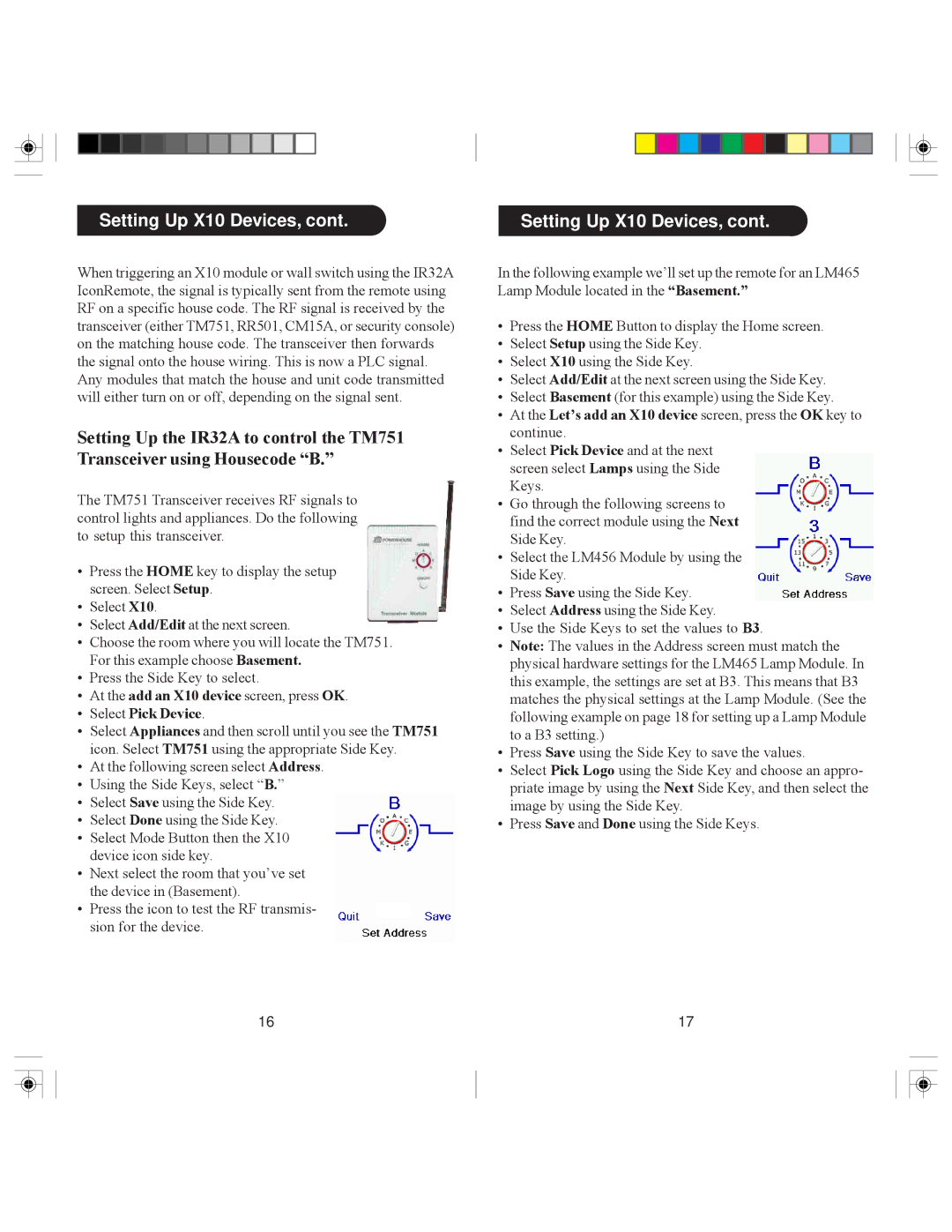
•Select Pick Device and at the next screen select Lamps using the Side Keys.
•Go through the following screens to find the correct module using the Next Side Key.
•Select the LM456 Module by using the Side Key.
•Press Save using the Side Key.
•Select Address using the Side Key.
•Use the Side Keys to set the values to B3.
•Note: The values in the Address screen must match the physical hardware settings for the LM465 Lamp Module. In this example, the settings are set at B3. This means that B3 matches the physical settings at the Lamp Module. (See the following example on page 18 for setting up a Lamp Module to a B3 setting.)
•Press Save using the Side Key to save the values.
•Select Pick Logo using the Side Key and choose an appro- priate image by using the Next Side Key, and then select the image by using the Side Key.
•Press Save and Done using the Side Keys.
16 | 17 |