SECTION 4
OPERATION
OPERATOR INTERFACE
The
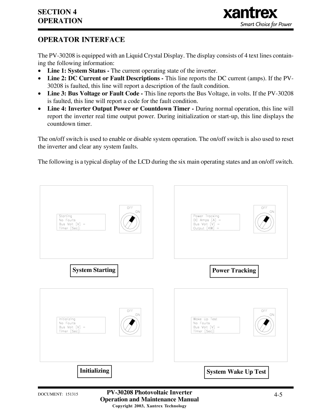
•Line 1: System Status - The current operating state of the inverter.
•Line 2: DC Current or Fault Descriptions - This line reports the DC current (amps). If the PV- 30208 is faulted, this line will report a description of the fault condition.
•Line 3: Bus Voltage or Fault Code - This line reports the Bus Voltage, in volts. If the
•Line 4: Inverter Output Power or Countdown Timer - During normal operation, this line will report the inverter real time output power. During initialization or
The on/off switch is used to enable or disable system operation. The on/off switch is also used to reset the inverter and clear any system faults.
The following is a typical display of the LCD during the six main operating states and an on/off switch.
System Starting
Power Tracking
Initializing
System Wake Up Test
DOCUMENT: 151315 | ||
| Operation and Maintenance Manual |
|
Copyright 2003, Xantrex Technology
