SECTION 4
OPERATION
Ground Fault Detection
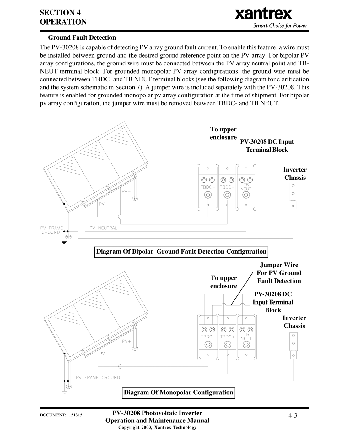
The PV-30208 is capable of detecting PV array ground fault current. To enable this feature, a wire must be installed between ground and the desired ground reference point on the PV array. For bipolar PV array configurations, the ground wire must be connected between the PV array neutral point and TB- NEUT terminal block. For grounded monopolar PV array configurations, the ground wire must be connected between TBDC- and TB NEUT terminal blocks (see the following diagram for clarification and the system schematic in Section 7). A jumper wire is included separately with the PV-30208. This feature is enabled for grounded monopolar pv array configuration at the time of shipment. For bipolar pv array configuration, the jumper wire must be removed between TBDC- and TB NEUT.
To upper
enclosure PV-30208 DC Input Terminal Block
Inverter
Chassis
Diagram Of Bipolar Ground Fault Detection Configuration
| | Jumper Wire |
| To upper | For PV Ground |
| Fault Detection |
| enclosure |
| PV-30208 DC |
| |
| | Input Terminal |
| | Block |
| | Inverter |
| | Chassis |
Diagram Of Monopolar Configuration
DOCUMENT: 151315 | PV-30208 Photovoltaic Inverter | 4-3 |
| Operation and Maintenance Manual | |
Copyright 2003, Xantrex Technology

