Current Sharing
Overview
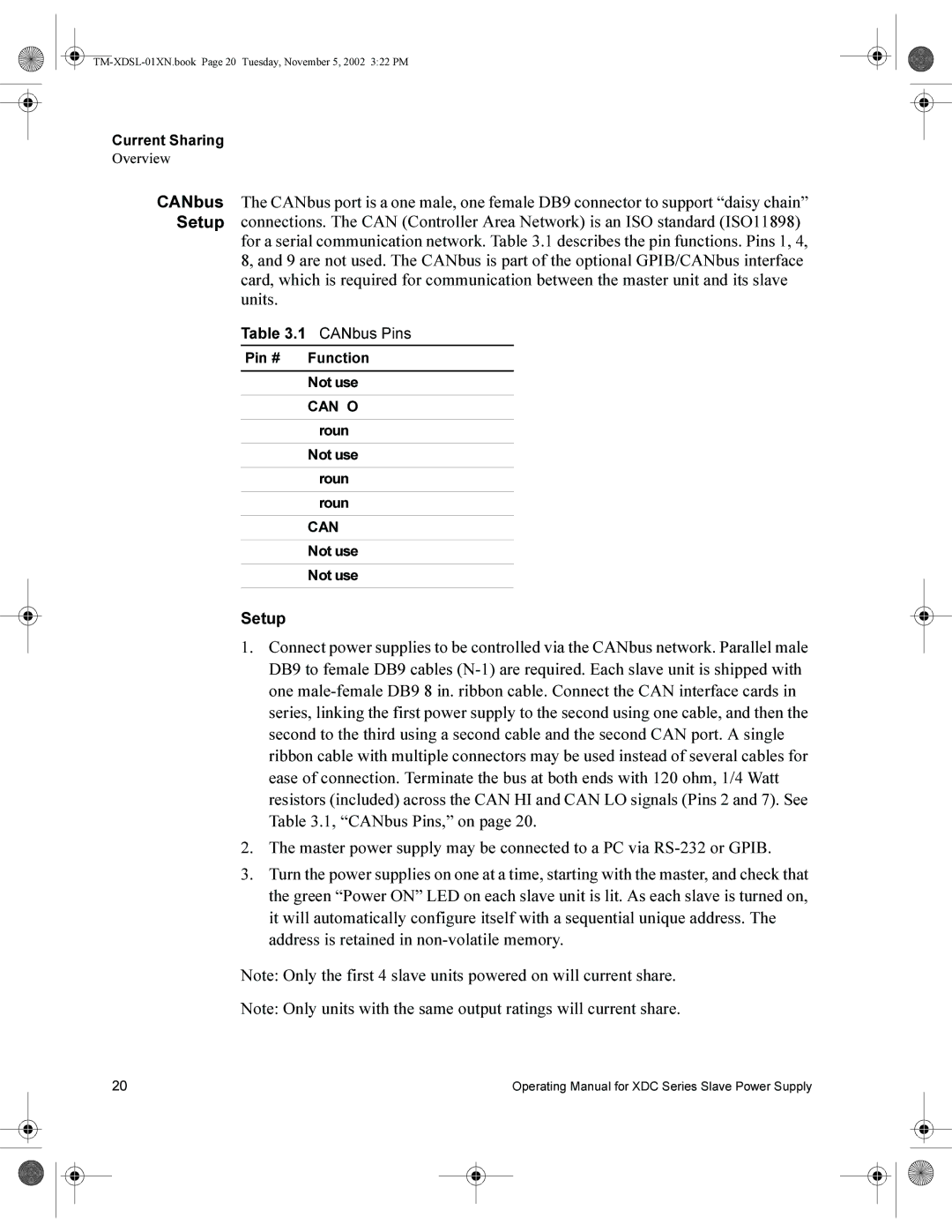
CANbus The CANbus port is a one male, one female DB9 connector to support “daisy chain” Setup connections. The CAN (Controller Area Network) is an ISO standard (ISO11898) for a serial communication network. Table 3.1 describes the pin functions. Pins 1, 4, 8, and 9 are not used. The CANbus is part of the optional GPIB/CANbus interface
card, which is required for communication between the master unit and its slave units.
Table 3.1 CANbus Pins
Pin # | Function |
1Not used
2CANLO
3Ground
4Not used
5Ground
6Ground
7CANHI
8Not used
9Not used
Setup
1.Connect power supplies to be controlled via the CANbus network. Parallel male DB9 to female DB9 cables
2.The master power supply may be connected to a PC via
3.Turn the power supplies on one at a time, starting with the master, and check that the green “Power ON” LED on each slave unit is lit. As each slave is turned on, it will automatically configure itself with a sequential unique address. The address is retained in
Note: Only the first 4 slave units powered on will current share.
Note: Only units with the same output ratings will current share.
20 | Operating Manual for XDC Series Slave Power Supply |