
DPX-1300 G specifications
The Yamaha DPX-1300 G is a cutting-edge digital projector designed for professional applications, combining advanced technology with high-quality performance. This projector is engineered to deliver vibrant visuals, making it an ideal choice for a variety of settings, including corporate presentations, educational environments, and large-scale events.One of the standout features of the Yamaha DPX-1300 G is its impressive brightness. With a lumens output that can reach up to 3000 ANSI lumens, the projector ensures clear and vivid images even in well-lit environments. This high brightness level, combined with its high contrast ratio, produces sharp details and rich colors that captivate audiences. The projector supports a variety of resolutions, including Full HD, ensuring compatibility with the latest content.
Incorporating Yamaha’s sophisticated optical technologies, the DPX-1300 G utilizes a 3LCD system that promises exceptional color accuracy and smooth image rendering. This technology minimizes the risk of color distortion and ensures that presentations remain true to their original intent. Additionally, the projector features advanced image processing capabilities, which enhance sharpness and reduce noise, providing a polished viewing experience.
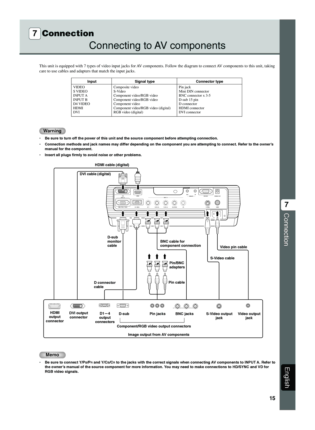
The DPX-1300 G supports multiple connectivity options, including HDMI, VGA, and USB, allowing seamless integration with various devices such as laptops, Blu-ray players, and media streaming devices. This versatility makes it a flexible solution for businesses and educational institutions that require compatibility with a range of presentation tools.
Another remarkable characteristic of the Yamaha DPX-1300 G is its user-friendly interface. The onboard menu provides easy access to settings and adjustments, making it straightforward for users to customize their display preferences. The projector also includes features like keystone correction and lens shift, enabling easy setup and alignment for optimal image placement.
Designed with longevity in mind, the DPX-1300 G features a long-lasting lamp that can provide thousands of hours of operational use, reducing maintenance requirements and total cost of ownership. Additionally, its compact and lightweight design facilitates easy transportation and setup.
In conclusion, the Yamaha DPX-1300 G stands out as a reliable and high-performing digital projector. With its exceptional brightness, advanced optical technologies, wide connectivity options, and user-friendly features, it is well-suited for any professional environment. Whether for corporate use, educational purposes, or events, this projector promises to deliver remarkable image quality and performance.