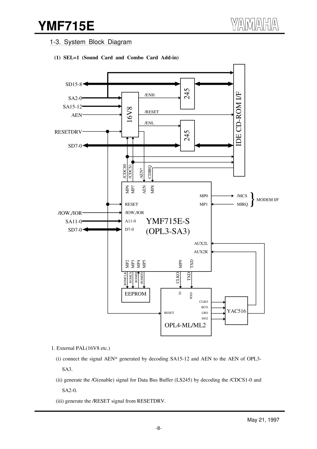
OPL3-SA3 specifications
The Yamaha OPL3-SA3 is a highly regarded sound card known for its exceptional audio performance and versatility, capturing the interest of enthusiasts and professionals in the digital audio realm. As an advanced version of the popular OPL3 series, the OPL3-SA3 integrates cutting-edge technologies that enhance its sound generation capabilities, making it a sought-after component for both music production and gaming applications.One of the key features of the Yamaha OPL3-SA3 is its use of the FM synthesis technology, which allows for the generation of rich, complex sounds that are particularly favored in electronic and video game music. The OPL3 architecture supports up to 18 channels of audio output, enabling the simultaneous playback of multiple sounds without compromising quality. This multichannel capability enhances its use in audio applications, where layering various sound elements is crucial.
In addition to its synthesis features, the OPL3-SA3 also incorporates advanced MIDI capabilities, allowing musicians to connect and control external MIDI devices seamlessly. The integration of General MIDI support expands its usability in various music production setups. This makes the OPL3-SA3 a versatile option for composers and sound designers looking to create intricate soundscapes or realistic instrument simulations.
The audio quality of the OPL3-SA3 is further complemented by its 16-bit resolution and a sampling rate of up to 44.1 kHz, delivering clear and dynamic audio playback. This high level of fidelity is essential for generating lifelike sounds, making it suitable for both professional recordings and high-quality gaming experiences.
Another notable characteristic of the OPL3-SA3 is its compatibility with a wide range of operating systems, including DOS and Windows platforms, enhancing its accessibility for users of different systems. The card's drivers are designed for simplicity and reliability, ensuring that it can be easily integrated into existing audio setups.
With its combination of FM synthesis, MIDI capabilities, multichannel support, and high-fidelity audio performance, the Yamaha OPL3-SA3 stands out as a powerful tool for sound generation. Whether utilized by musicians, audio engineers, or game developers, the OPL3-SA3 continues to be a valuable asset in the evolving landscape of digital audio. Its legacy in the realm of sound cards remains influential, showcasing Yamaha's commitment to innovation and quality in the field of audio technology.

