CONNECTIONS
Before Connecting Components
CAUTION
Never connect this unit and other components to mains power until all connections between components have been completed.
Be sure all connections are made correctly, that is to say L (left) to L, R (right) to R, “+” to “+” and
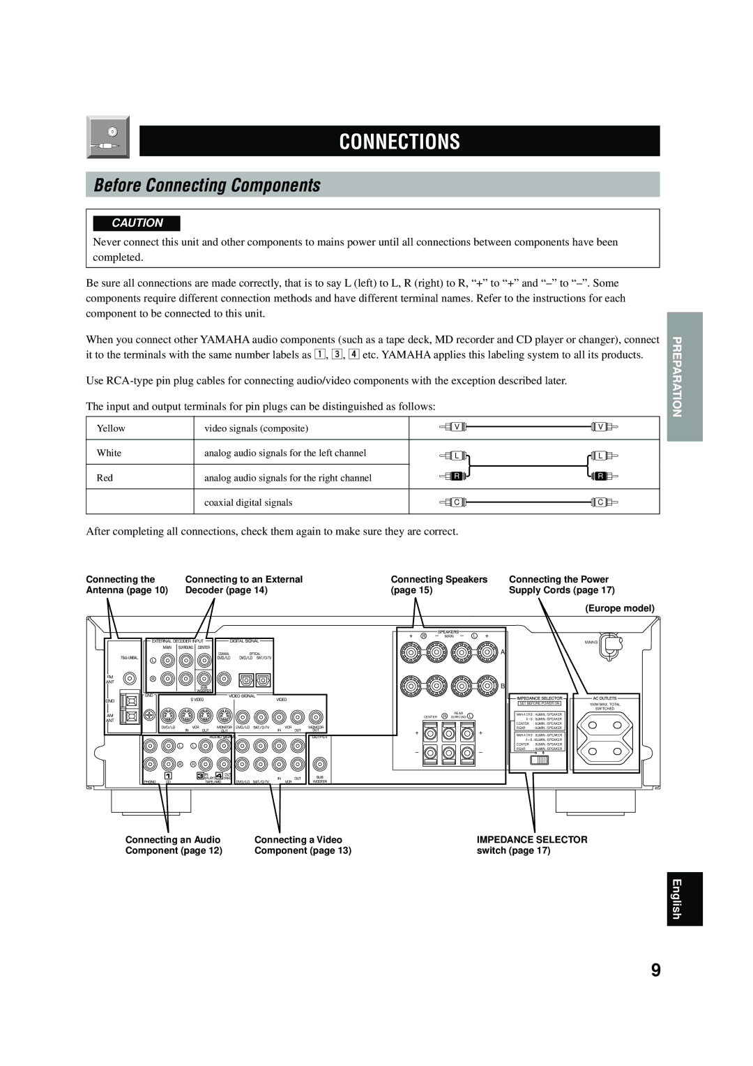
When you connect other YAMAHA audio components (such as a tape deck, MD recorder and CD player or changer), connect it to the terminals with the same number labels as !, #, $ etc. YAMAHA applies this labeling system to all its products.
Use
The input and output terminals for pin plugs can be distinguished as follows:
Yellow | video signals (composite) | V | V |
White | analog audio signals for the left channel | L | L |
Red | analog audio signals for the right channel | R | R |
| coaxial digital signals | C | C |
PREPARATION
After completing all connections, check them again to make sure they are correct.
Connecting the | Connecting to an External | Connecting Speakers | Connecting the Power |
Antenna (page 10) | Decoder (page 14) | (page 15) | Supply Cords (page 17) |
(Europe model)
+ | R | – | MAIN | – | L | + |
|
| |
|
|
|
|
|
|
|
|
| MAINS |
|
|
|
|
|
|
| A |
|
|
|
|
|
|
|
|
| B |
|
|
|
|
|
|
|
|
| SET BEFORE POWER ON | 100W MAX. TOTAL | |
|
|
|
|
|
|
|
|
| SWITCHED |
| CENTER | R |
| REAR | L | MAIN A OR B : 4ΩMIN. /SPEAKER |
| ||
| (SURROUND) | A + B : 8ΩMIN. /SPEAKER |
| ||||||
|
|
|
|
|
|
|
| ||
|
|
|
|
|
|
| CENTER | : 6ΩMIN. /SPEAKER |
|
| + |
|
|
|
| + | REAR | : 6ΩMIN. /SPEAKER |
|
|
|
|
|
| MAIN A OR B : 8ΩMIN. /SPEAKER |
| |||
|
|
|
|
|
|
| A + B : I6ΩMIN. /SPEAKER |
| |
|
|
|
|
|
|
| CENTER | : 8ΩMIN. /SPEAKER |
|
| – |
|
|
|
| – | REAR | : 8ΩMIN. /SPEAKER |
|
|
|
|
|
|
|
|
| ||
Connecting an Audio | Connecting a Video | IMPEDANCE SELECTOR |
Component (page 12) | Component (page 13) | switch (page 17) |
English
9