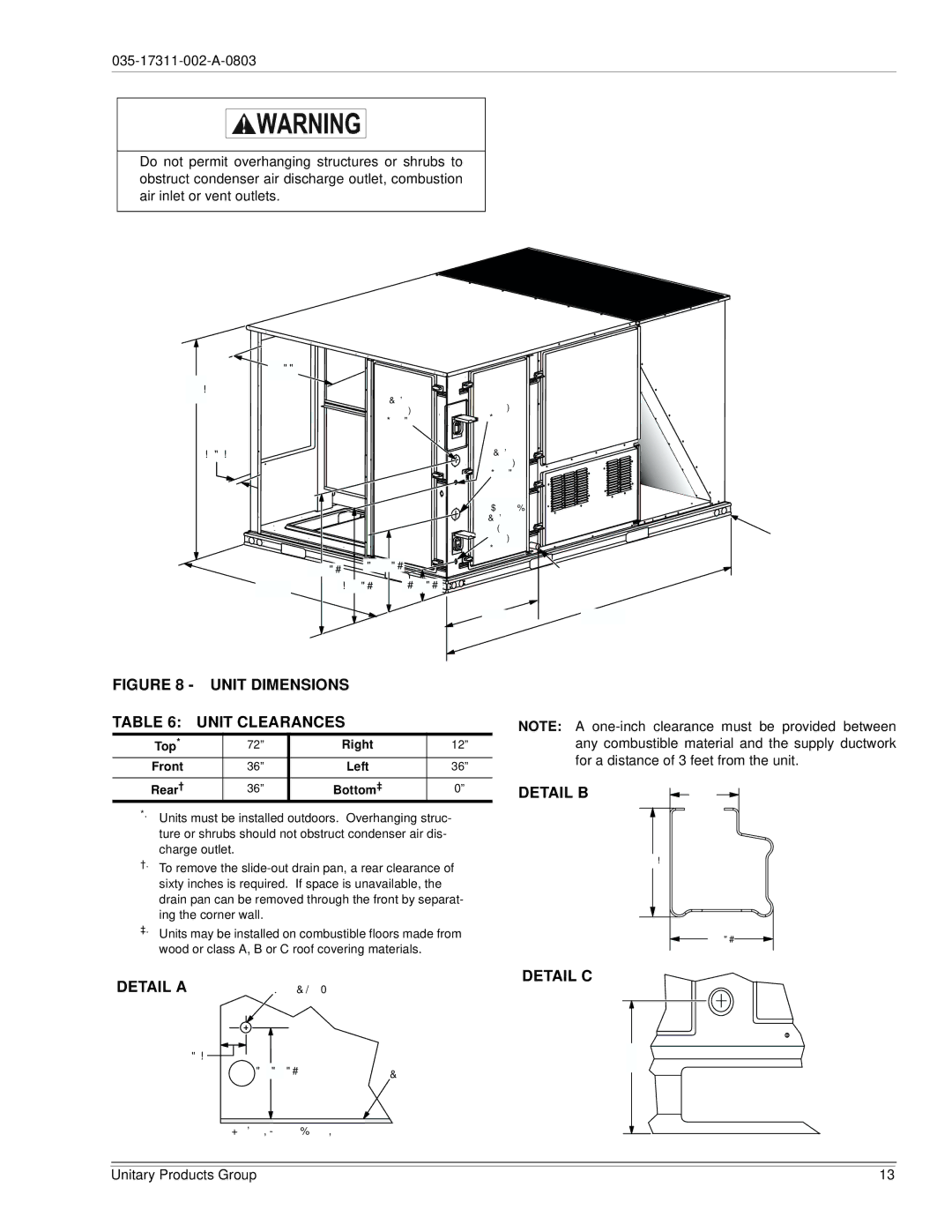
Do not permit overhanging structures or shrubs to obstruct condenser air discharge outlet, combustion air inlet or vent outlets.
| Power | Control |
| Entry | |
| Entry | |
| Ø7/8 | |
| ||
|
| |
| Power | |
|
| Entry |
|
|
![]() Convenience Power Outlet Entry Ø7/8
Convenience Power Outlet Entry Ø7/8
| |||
|
|
| |
59 | |||
|
|
| |
LEFT
27
ForBaserail
Dimensions
FRONT SeeDetailA
ForDrain
Dimensions
SeeDetailB
89
FIGURE 8 - UNIT DIMENSIONS |
| |||
TABLE 6: | UNIT CLEARANCES |
| ||
|
|
|
|
|
Top* |
| 72” | Right | 12” |
Front |
| 36” | Left | 36” |
|
|
|
|
|
Rear† |
| 36” | Bottom‡ | 0” |
*. Units must be installed outdoors. Overhanging struc- ture or shrubs should not obstruct condenser air dis- charge outlet.
†.To remove the
‡.Units may be installed on combustible floors made from wood or class A, B or C roof covering materials.
DETAIL A | GasPipeInlet |
![]()
Base
NOTE: A
DETAIL B | |
|
DETAIL C
ViewofWalAcrossfromCoil
Unitary Products Group | 13 |