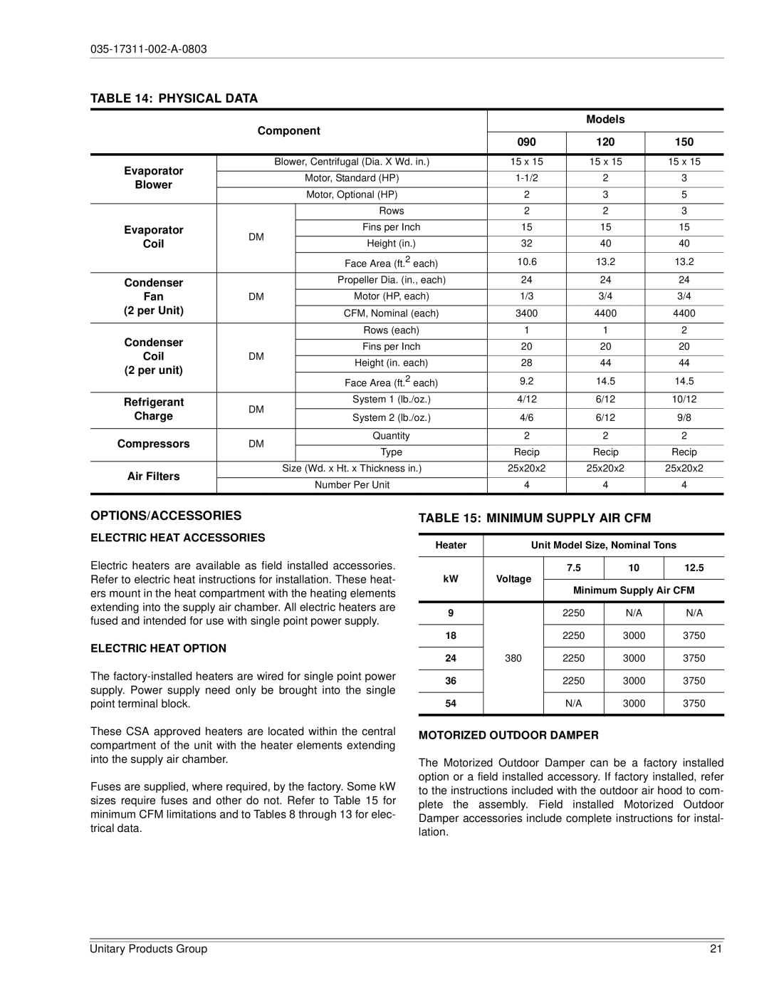
TABLE 14: PHYSICAL DATA
| Component |
| Models |
| ||
|
|
|
| |||
| 090 | 120 | 150 | |||
|
|
|
| |||
|
|
|
|
|
|
|
Evaporator |
| Blower, Centrifugal (Dia. X Wd. in.) | 15 x 15 | 15 x 15 | 15 x 15 | |
|
|
|
|
|
| |
|
| Motor, Standard (HP) | 2 | 3 | ||
Blower |
|
| ||||
|
|
|
|
|
| |
|
| Motor, Optional (HP) | 2 | 3 | 5 | |
|
|
| ||||
|
|
|
|
|
|
|
|
|
| Rows | 2 | 2 | 3 |
|
|
|
|
|
|
|
Evaporator | DM |
| Fins per Inch | 15 | 15 | 15 |
Coil |
| Height (in.) | 32 | 40 | 40 | |
|
| |||||
|
|
|
|
|
|
|
|
|
| Face Area (ft.2 each) | 10.6 | 13.2 | 13.2 |
Condenser |
|
| Propeller Dia. (in., each) | 24 | 24 | 24 |
Fan | DM |
| Motor (HP, each) | 1/3 | 3/4 | 3/4 |
(2 per Unit) |
|
|
|
|
|
|
|
| CFM, Nominal (each) | 3400 | 4400 | 4400 | |
|
|
|
|
|
|
|
Condenser |
|
| Rows (each) | 1 | 1 | 2 |
|
|
|
|
|
| |
|
| Fins per Inch | 20 | 20 | 20 | |
Coil | DM |
| ||||
|
|
|
|
| ||
| Height (in. each) | 28 | 44 | 44 | ||
(2 per unit) |
|
| ||||
|
|
|
|
|
| |
|
| Face Area (ft.2 each) | 9.2 | 14.5 | 14.5 | |
|
|
| ||||
Refrigerant | DM |
| System 1 (lb./oz.) | 4/12 | 6/12 | 10/12 |
Charge |
| System 2 (lb./oz.) | 4/6 | 6/12 | 9/8 | |
|
| |||||
|
|
|
|
|
|
|
Compressors | DM |
| Quantity | 2 | 2 | 2 |
|
|
|
|
| ||
| Type | Recip | Recip | Recip | ||
|
|
| ||||
|
|
|
|
|
|
|
Air Filters |
| Size (Wd. x Ht. x Thickness in.) | 25x20x2 | 25x20x2 | 25x20x2 | |
|
|
|
|
|
| |
|
| Number Per Unit | 4 | 4 | 4 | |
|
|
| ||||
|
|
|
|
|
|
|
OPTIONS/ACCESSORIES
ELECTRIC HEAT ACCESSORIES
Electric heaters are available as field installed accessories. Refer to electric heat instructions for installation. These heat- ers mount in the heat compartment with the heating elements extending into the supply air chamber. All electric heaters are fused and intended for use with single point power supply.
ELECTRIC HEAT OPTION
The
These CSA approved heaters are located within the central compartment of the unit with the heater elements extending into the supply air chamber.
Fuses are supplied, where required, by the factory. Some kW sizes require fuses and other do not. Refer to Table 15 for minimum CFM limitations and to Tables 8 through 13 for elec- trical data.
TABLE 15: MINIMUM SUPPLY AIR CFM
Heater |
| Unit Model Size, Nominal Tons |
| ||||
|
|
|
|
|
| ||
kW | Voltage | 7.5 | 10 |
| 12.5 | ||
|
|
|
| ||||
Minimum Supply Air CFM | |||||||
|
|
| |||||
|
|
|
|
|
|
| |
9 |
|
| 2250 | N/A |
| N/A | |
|
|
|
|
|
|
| |
18 |
|
| 2250 | 3000 |
| 3750 | |
|
|
|
|
|
|
| |
24 | 380 |
| 2250 | 3000 |
| 3750 | |
|
|
|
|
|
|
| |
36 |
|
| 2250 | 3000 |
| 3750 | |
|
|
|
|
|
|
| |
54 |
|
| N/A | 3000 |
| 3750 | |
|
|
|
|
|
|
| |
MOTORIZED OUTDOOR DAMPER
The Motorized Outdoor Damper can be a factory installed option or a field installed accessory. If factory installed, refer to the instructions included with the outdoor air hood to com- plete the assembly. Field installed Motorized Outdoor Damper accessories include complete instructions for instal- lation.
Unitary Products Group | 21 |