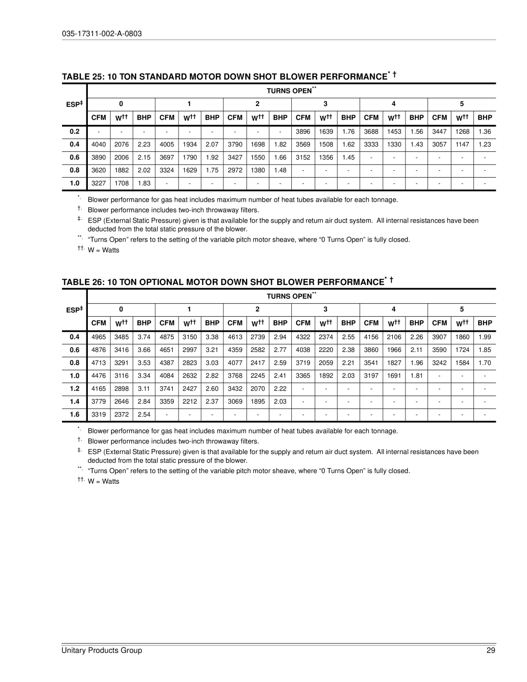
TABLE 25: 10 TON STANDARD MOTOR DOWN SHOT BLOWER PERFORMANCE* †
|
|
|
|
|
|
|
|
| TURNS OPEN** |
|
|
|
|
|
|
|
| |||
ESP‡ |
| 0 |
|
| 1 |
|
| 2 |
|
|
|
| 3 |
|
| 4 |
|
| 5 |
|
| CFM | W†† | BHP | CFM | W†† | BHP | CFM | W†† |
| BHP | CFM |
| W†† | BHP | CFM | W†† | BHP | CFM | W†† | BHP |
0.2 | - | - | - | - | - | - | - | - |
| - | 3896 |
| 1639 | 1.76 | 3688 | 1453 | 1.56 | 3447 | 1268 | 1.36 |
|
|
|
|
|
|
|
|
|
|
|
|
|
|
|
|
|
|
|
|
|
0.4 | 4040 | 2076 | 2.23 | 4005 | 1934 | 2.07 | 3790 | 1698 |
| 1.82 | 3569 |
| 1508 | 1.62 | 3333 | 1330 | 1.43 | 3057 | 1147 | 1.23 |
|
|
|
|
|
|
|
|
|
|
|
|
|
|
|
|
|
|
|
|
|
0.6 | 3890 | 2006 | 2.15 | 3697 | 1790 | 1.92 | 3427 | 1550 |
| 1.66 | 3152 |
| 1356 | 1.45 | - | - | - | - | - | - |
|
|
|
|
|
|
|
|
|
|
|
|
|
|
|
|
|
|
|
|
|
0.8 | 3620 | 1882 | 2.02 | 3324 | 1629 | 1.75 | 2972 | 1380 |
| 1.48 | - |
| - | - | - | - | - | - | - | - |
|
|
|
|
|
|
|
|
|
|
|
|
|
|
|
|
|
|
|
|
|
1.0 | 3227 | 1708 | 1.83 | - | - | - | - | - |
| - | - |
| - | - | - | - | - | - | - | - |
|
|
|
|
|
|
|
|
|
|
|
|
|
|
|
|
|
|
|
|
|
*.
†.Blower performance includes
‡.ESP (External Static Pressure) given is that available for the supply and return air duct system. All internal resistances have been deducted from the total static pressure of the blower.
**. “Turns Open” refers to the setting of the variable pitch motor sheave, where “0 Turns Open” is fully closed.
††.W = Watts
TABLE 26: 10 TON OPTIONAL MOTOR DOWN SHOT BLOWER PERFORMANCE* †
|
|
|
|
|
|
|
|
| TURNS OPEN** |
|
|
|
|
|
|
|
| |||
ESP‡ |
| 0 |
|
| 1 |
|
| 2 |
|
|
|
| 3 |
|
| 4 |
|
| 5 |
|
| CFM | W†† | BHP | CFM | W†† | BHP | CFM | W†† |
| BHP | CFM |
| W†† | BHP | CFM | W†† | BHP | CFM | W†† | BHP |
0.4 | 4965 | 3485 | 3.74 | 4875 | 3150 | 3.38 | 4613 | 2739 |
| 2.94 | 4322 |
| 2374 | 2.55 | 4156 | 2106 | 2.26 | 3907 | 1860 | 1.99 |
|
|
|
|
|
|
|
|
|
|
|
|
|
|
|
|
|
|
|
|
|
0.6 | 4876 | 3416 | 3.66 | 4651 | 2997 | 3.21 | 4359 | 2582 |
| 2.77 | 4038 |
| 2220 | 2.38 | 3860 | 1966 | 2.11 | 3590 | 1724 | 1.85 |
|
|
|
|
|
|
|
|
|
|
|
|
|
|
|
|
|
|
|
|
|
0.8 | 4713 | 3291 | 3.53 | 4387 | 2823 | 3.03 | 4077 | 2417 |
| 2.59 | 3719 |
| 2059 | 2.21 | 3541 | 1827 | 1.96 | 3242 | 1584 | 1.70 |
|
|
|
|
|
|
|
|
|
|
|
|
|
|
|
|
|
|
|
|
|
1.0 | 4476 | 3116 | 3.34 | 4084 | 2632 | 2.82 | 3768 | 2245 |
| 2.41 | 3365 |
| 1892 | 2.03 | 3197 | 1691 | 1.81 | - | - | - |
|
|
|
|
|
|
|
|
|
|
|
|
|
|
|
|
|
|
|
|
|
1.2 | 4165 | 2898 | 3.11 | 3741 | 2427 | 2.60 | 3432 | 2070 |
| 2.22 | - |
| - | - | - | - | - | - | - | - |
|
|
|
|
|
|
|
|
|
|
|
|
|
|
|
|
|
|
|
|
|
1.4 | 3779 | 2646 | 2.84 | 3359 | 2212 | 2.37 | 3069 | 1895 |
| 2.03 | - |
| - | - | - | - | - | - | - | - |
|
|
|
|
|
|
|
|
|
|
|
|
|
|
|
|
|
|
|
|
|
1.6 | 3319 | 2372 | 2.54 | - | - | - | - | - |
| - | - |
| - | - | - | - | - | - | - | - |
|
|
|
|
|
|
|
|
|
|
|
|
|
|
|
|
|
|
|
|
|
*.
†.Blower performance includes
‡.ESP (External Static Pressure) given is that available for the supply and return air duct system. All internal resistances have been deducted from the total static pressure of the blower.
**. “Turns Open” refers to the setting of the variable pitch motor sheave, where “0 Turns Open” is fully closed.
††.W = Watts
Unitary Products Group | 29 |