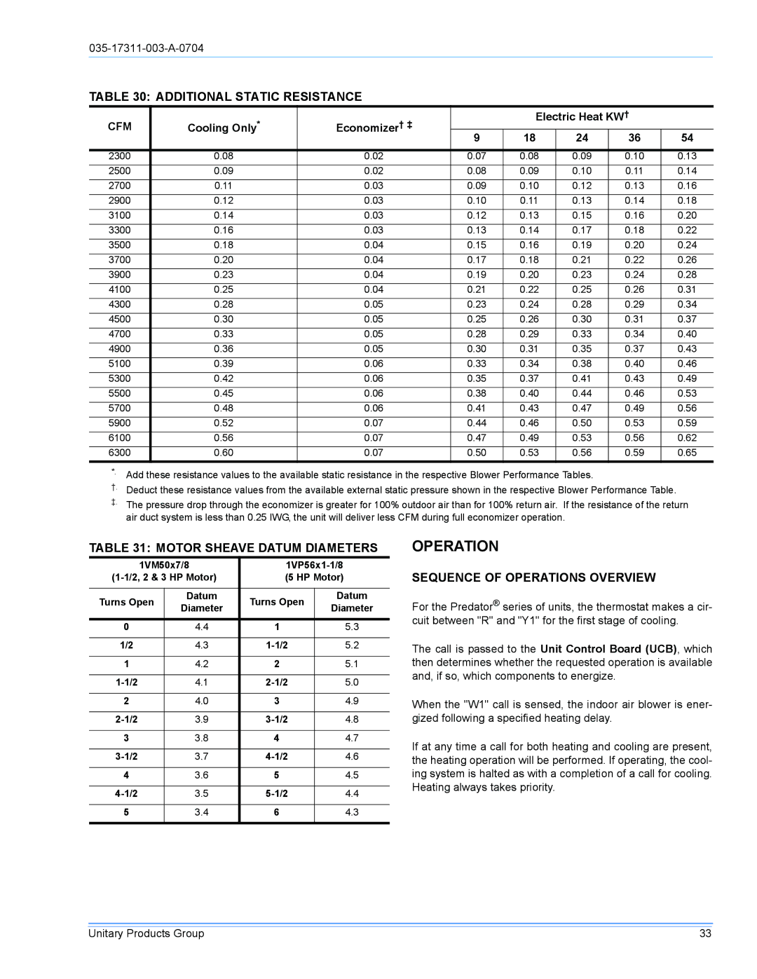
TABLE 30: ADDITIONAL STATIC RESISTANCE
CFM | Cooling Only* | Economizer† ‡ |
| Electric Heat KW† |
| |||
9 | 18 | 24 | 36 | 54 | ||||
|
|
| ||||||
|
|
|
|
|
|
|
| |
2300 | 0.08 | 0.02 | 0.07 | 0.08 | 0.09 | 0.10 | 0.13 | |
2500 | 0.09 | 0.02 | 0.08 | 0.09 | 0.10 | 0.11 | 0.14 | |
2700 | 0.11 | 0.03 | 0.09 | 0.10 | 0.12 | 0.13 | 0.16 | |
2900 | 0.12 | 0.03 | 0.10 | 0.11 | 0.13 | 0.14 | 0.18 | |
3100 | 0.14 | 0.03 | 0.12 | 0.13 | 0.15 | 0.16 | 0.20 | |
3300 | 0.16 | 0.03 | 0.13 | 0.14 | 0.17 | 0.18 | 0.22 | |
3500 | 0.18 | 0.04 | 0.15 | 0.16 | 0.19 | 0.20 | 0.24 | |
3700 | 0.20 | 0.04 | 0.17 | 0.18 | 0.21 | 0.22 | 0.26 | |
3900 | 0.23 | 0.04 | 0.19 | 0.20 | 0.23 | 0.24 | 0.28 | |
4100 | 0.25 | 0.04 | 0.21 | 0.22 | 0.25 | 0.26 | 0.31 | |
4300 | 0.28 | 0.05 | 0.23 | 0.24 | 0.28 | 0.29 | 0.34 | |
4500 | 0.30 | 0.05 | 0.25 | 0.26 | 0.30 | 0.31 | 0.37 | |
4700 | 0.33 | 0.05 | 0.28 | 0.29 | 0.33 | 0.34 | 0.40 | |
4900 | 0.36 | 0.05 | 0.30 | 0.31 | 0.35 | 0.37 | 0.43 | |
5100 | 0.39 | 0.06 | 0.33 | 0.34 | 0.38 | 0.40 | 0.46 | |
5300 | 0.42 | 0.06 | 0.35 | 0.37 | 0.41 | 0.43 | 0.49 | |
5500 | 0.45 | 0.06 | 0.38 | 0.40 | 0.44 | 0.46 | 0.53 | |
5700 | 0.48 | 0.06 | 0.41 | 0.43 | 0.47 | 0.49 | 0.56 | |
5900 | 0.52 | 0.07 | 0.44 | 0.46 | 0.50 | 0.53 | 0.59 | |
6100 | 0.56 | 0.07 | 0.47 | 0.49 | 0.53 | 0.56 | 0.62 | |
6300 | 0.60 | 0.07 | 0.50 | 0.53 | 0.56 | 0.59 | 0.65 | |
*. Add these resistance values to the available static resistance in the respective Blower Performance Tables.
†.Deduct these resistance values from the available external static pressure shown in the respective Blower Performance Table.
‡.The pressure drop through the economizer is greater for 100% outdoor air than for 100% return air. If the resistance of the return air duct system is less than 0.25 IWG, the unit will deliver less CFM during full economizer operation.
TABLE 31: MOTOR SHEAVE DATUM DIAMETERS
| 1VM50x7/8 | ||||
(5 HP Motor) | |||||
|
|
|
|
| |
Turns Open | Datum | Turns Open | Datum | ||
Diameter | Diameter | ||||
|
|
| |||
|
|
|
|
| |
0 |
| 4.4 | 1 | 5.3 | |
|
|
|
|
| |
1/2 |
| 4.3 | 5.2 | ||
|
|
|
|
| |
1 |
| 4.2 | 2 | 5.1 | |
|
|
|
|
| |
| 4.1 | 5.0 | |||
|
|
|
|
| |
2 |
| 4.0 | 3 | 4.9 | |
|
|
|
|
| |
| 3.9 | 4.8 | |||
|
|
|
|
| |
3 |
| 3.8 | 4 | 4.7 | |
|
|
|
|
| |
| 3.7 | 4.6 | |||
|
|
|
|
| |
4 |
| 3.6 | 5 | 4.5 | |
|
|
|
|
| |
| 3.5 | 4.4 | |||
|
|
|
|
| |
5 |
| 3.4 | 6 | 4.3 | |
|
|
|
|
| |
OPERATION
SEQUENCE OF OPERATIONS OVERVIEW
For the Predator® series of units, the thermostat makes a cir- cuit between "R" and "Y1" for the first stage of cooling.
The call is passed to the Unit Control Board (UCB), which then determines whether the requested operation is available and, if so, which components to energize.
When the "W1" call is sensed, the indoor air blower is ener- gized following a specified heating delay.
If at any time a call for both heating and cooling are present, the heating operation will be performed. If operating, the cool- ing system is halted as with a completion of a call for cooling. Heating always takes priority.
Unitary Products Group | 33 |
