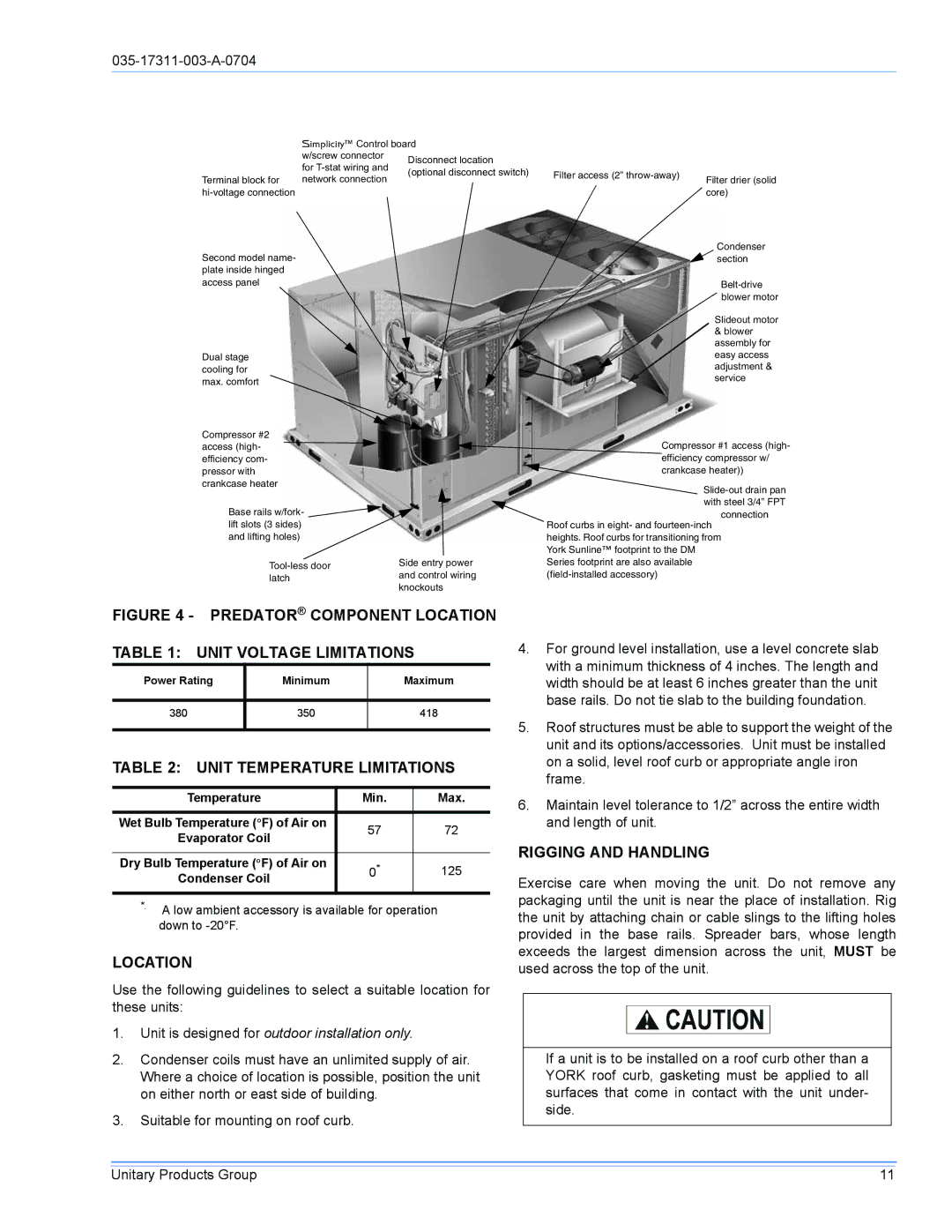
| Simplicity™ Control board | ||
| w/screw connector | Disconnect location | |
| for | ||
| (optional disconnect switch) | ||
Terminal block for | network connection | ||
| |||
Second model name- plate inside hinged access panel
Dual stage cooling for max. comfort
Compressor #2 access (high- efficiency com- pressor with crankcase heater
Base rails w/fork- lift slots (3 sides) and lifting holes)
Side entry power | ||
and control wiring | ||
latch | ||
knockouts | ||
|
Filter access (2” | Filter drier (solid |
| |
| core) |
Condenser section
Slideout motor & blower assembly for easy access adjustment & service
Compressor #1 access (high- efficiency compressor w/ crankcase heater))
Roof curbs in eight- and
FIGURE 4 - PREDATOR® COMPONENT LOCATION
TABLE 1: UNIT VOLTAGE LIMITATIONS
Power Rating | Minimum | Maximum |
|
|
|
380 | 350 | 418 |
|
|
|
TABLE 2: UNIT TEMPERATURE LIMITATIONS
Temperature | Min. | Max. | |
|
|
| |
Wet Bulb Temperature (°F) of Air on | 57 | 72 | |
Evaporator Coil | |||
|
| ||
|
|
| |
Dry Bulb Temperature (°F) of Air on | 0* | 125 | |
Condenser Coil | |||
|
| ||
|
|
|
*. A low ambient accessory is available for operation down to
LOCATION
Use the following guidelines to select a suitable location for these units:
1.Unit is designed for outdoor installation only.
2.Condenser coils must have an unlimited supply of air. Where a choice of location is possible, position the unit on either north or east side of building.
3.Suitable for mounting on roof curb.
4.For ground level installation, use a level concrete slab with a minimum thickness of 4 inches. The length and width should be at least 6 inches greater than the unit base rails. Do not tie slab to the building foundation.
5.Roof structures must be able to support the weight of the unit and its options/accessories. Unit must be installed on a solid, level roof curb or appropriate angle iron frame.
6.Maintain level tolerance to 1/2” across the entire width and length of unit.
RIGGING AND HANDLING
Exercise care when moving the unit. Do not remove any packaging until the unit is near the place of installation. Rig the unit by attaching chain or cable slings to the lifting holes provided in the base rails. Spreader bars, whose length exceeds the largest dimension across the unit, MUST be used across the top of the unit.
If a unit is to be installed on a roof curb other than a YORK roof curb, gasketing must be applied to all surfaces that come in contact with the unit under- side.
Unitary Products Group | 11 |