a compressor too soon after its previous run. Additionally, a minimum run time is imposed any time a compressor is ener- gized.
The ASCD is initiated on unit
FLASH CODES
The UCB will initiate a flash code associated with errors within the system. Refer to UNIT CONTROL BOARD FLASH CODES 37.
RESET
Remove the call for cooling, by raising thermostat setting higher than the conditioned space temperature. This resets any pressure or freezestat flash codes.
ELECTRIC HEATING SEQUENCE OF OPERATIONS
The following sequence describes the operation of the elec- tric heat section.
a.Upon a call for first stage heat by the thermostat, the heater relay (RA) will be energized. After completing the specified fan on delay for heating, the UCB will energize the blower motor. If the second stage of heat is required, heater relay (RB) will be energized. After completing the specified fan on delay for heat- ing, the UCB will energize the blower motor.
b.The thermostat will cycle the electric heat to satisfy the heating requirements of the conditioned space.
ELECTRIC HEATING OPERATION ERRORS
TEMPERATURE LIMIT
If the UCB senses zero volts from the high temperature limit, the indoor blower motor is immediately energized.
This limit is monitored regardless of unit operation status, i.e. the limit is monitored at all times.
If the temperature limit opens three times within one hour, it will
SAFETY CONTROLS
The UCB monitors the temperature limit switch of electric heat units.
The control circuit includes the following safety controls:
LIMIT SWITCH (LS)
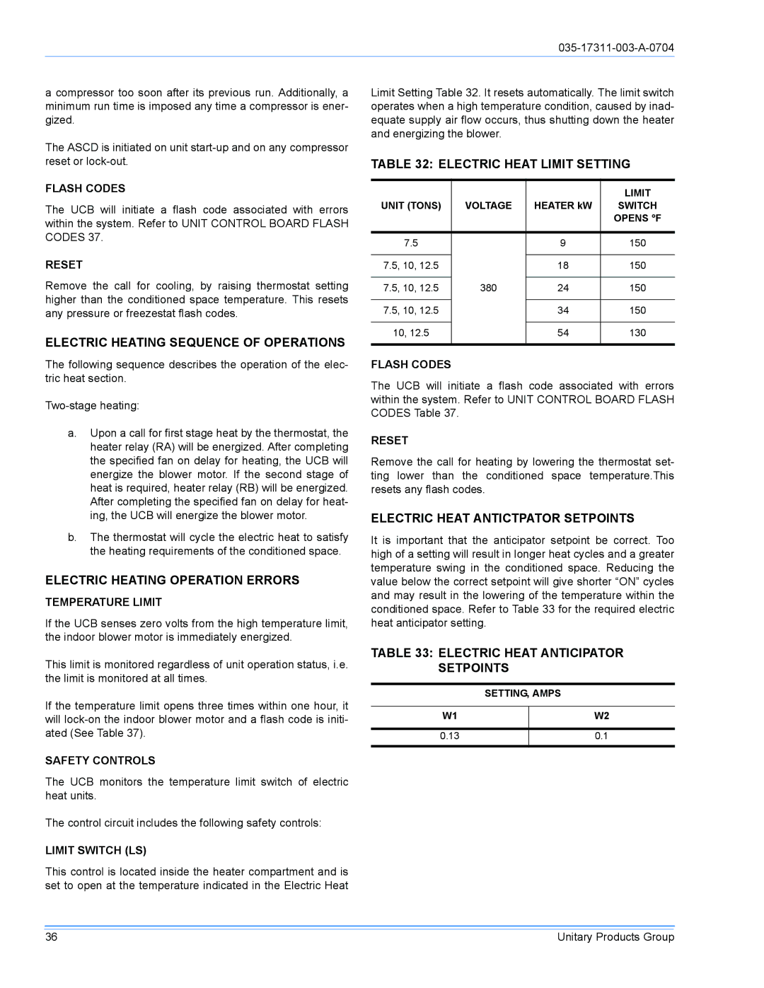
This control is located inside the heater compartment and is set to open at the temperature indicated in the Electric Heat
Limit Setting Table 32. It resets automatically. The limit switch operates when a high temperature condition, caused by inad- equate supply air flow occurs, thus shutting down the heater and energizing the blower.
TABLE 32: ELECTRIC HEAT LIMIT SETTING
|
|
| LIMIT |
UNIT (TONS) | VOLTAGE | HEATER kW | SWITCH |
|
|
| OPENS °F |
|
|
|
|
7.5 |
| 9 | 150 |
|
|
|
|
7.5, 10, 12.5 |
| 18 | 150 |
|
|
|
|
7.5, 10, 12.5 | 380 | 24 | 150 |
|
|
|
|
7.5, 10, 12.5 |
| 34 | 150 |
|
|
|
|
10, 12.5 |
| 54 | 130 |
|
|
|
|
FLASH CODES
The UCB will initiate a flash code associated with errors within the system. Refer to UNIT CONTROL BOARD FLASH CODES Table 37.
RESET
Remove the call for heating by lowering the thermostat set- ting lower than the conditioned space temperature.This resets any flash codes.
ELECTRIC HEAT ANTICTPATOR SETPOINTS
It is important that the anticipator setpoint be correct. Too high of a setting will result in longer heat cycles and a greater temperature swing in the conditioned space. Reducing the value below the correct setpoint will give shorter “ON” cycles and may result in the lowering of the temperature within the conditioned space. Refer to Table 33 for the required electric heat anticipator setting.
TABLE 33: ELECTRIC HEAT ANTICIPATOR SETPOINTS
| SETTING, AMPS | |
|
|
|
W1 |
| W2 |
|
|
|
0.13 |
| 0.1 |
|
|
|
36 | Unitary Products Group |