York DM090 Side Panels With Hole Plugs, Condensate Drain Compressors, Filters

Models: DM090

1 44
Download 44 pages 9.47 Kb
Page 16
Image 16
FIGURE 13 - SIDE PANELS WITH HOLE PLUGS

035-17311-003-A-0704

When fastening ductwork to side duct flanges on unit, insert screws through duct flanges only. DO NOT insert screws through casing. Outdoor duct- work must be insulated and water-proofed.

FIGURE 13 - SIDE PANELS WITH HOLE PLUGS

Note orientation. Panel is “insulation” side up.
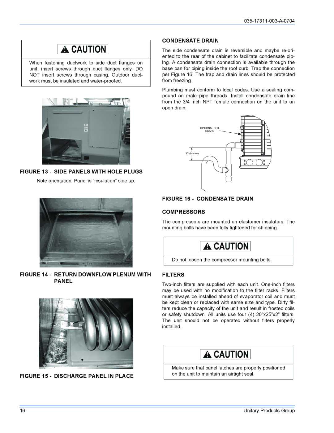
CONDENSATE DRAIN

The side condensate drain is reversible and maybe re-ori- ented to the rear of the cabinet to facilitate condensate pip- ing. A condensate drain connection is available through the base pan for piping inside the roof curb. Trap the connection per Figure 16. The trap and drain lines should be protected from freezing.

Plumbing must conform to local codes. Use a sealing com- pound on male pipe threads. Install condensate drain line from the 3/4 inch NPT female connection on the unit to an open drain.

OPTIONALCOIL

GUARD

3"Minimum

FIGURE 16 - CONDENSATE DRAIN

COMPRESSORS

The compressors are mounted on elastomer insulators. The mounting bolts have been fully tightened for shipping.

Do not loosen the compressor mounting bolts.

FIGURE 14 - RETURN DOWNFLOW PLENUM WITH PANEL

FILTERS

Two-inch filters are supplied with each unit. One-inch filters may be used with no modification to the filter racks. Filters must always be installed ahead of evaporator coil and must be kept clean or replaced with same size and type. Dirty fil- ters reduce the capacity of the unit and result in frosted coils or safety shutdown. All units use four (4) 20”x25”x2” filters. The unit should not be operated without filters properly installed.

FIGURE 15 - DISCHARGE PANEL IN PLACE

Make sure that panel latches are properly positioned on the unit to maintain an airtight seal.

16

Unitary Products Group

Page 16
Image 16
York DM090 Side Panels With Hole Plugs, Condensate Drain Compressors, Return Downflow Plenum With Panel, Filters