START-UP (COOLING)
PRESTART CHECK LIST
After installation has been completed:
1.Check the electrical supply voltage being supplied. Be sure that it is the same as listed on the unit nameplate.
2.Set the room thermostat to the off position.
3.Turn unit electrical power on.
4.Set the room thermostat fan switch to on.
5.Check indoor blower rotation.
•If blower rotation is in the wrong direction. Refer to Phasing Section in general information section.
•Check blower drive belt tension.
6.Check the unit supply air (CFM).
7.Measure evaporator fan motor's amp draw.
8.Set the room thermostat fan switch to off.
9.Turn unit electrical power off.
OPERATING INSTRUCTIONS
1.Turn unit electrical power on.
NOTE: Prior to each cooling season, the crankcase heaters must be energized at least 10 hours before the sys- tem is put into operation.
2.Set the room thermostat setting to lower than the room temperature.
3.First stage compressors will energize after the
4.The second stage of the thermostat will energize second stage compressor if needed.
POST START CHECK LIST
1.Verify proper system pressures for both circuits.
2.Measure the temperature drop across the evaporator coil.
CHARGING THE UNIT
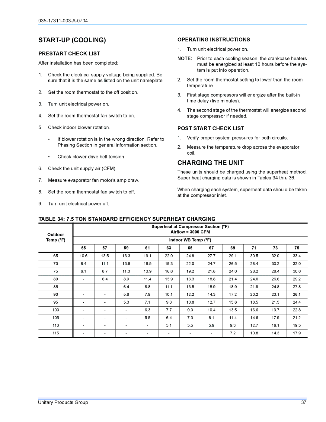
These units should be charged using the superheat method. Super heat charging data is shown in Tables 34 thru 36.
When charging each system, superheat data should be taken at the compressor inlet.
TABLE 34: 7.5 TON STANDARD EFFICIENCY SUPERHEAT CHARGING
|
|
|
|
| Superheat at Compressor Suction (°F) |
|
|
|
| ||||
Outdoor |
|
|
|
|
| Airflow = 3000 CFM |
|
|
|
| |||
|
|
|
|
|
|
|
|
|
|
|
|
| |
Temp (°F) |
|
|
|
|
| Indoor WB Temp (°F) |
|
|
|
| |||
|
|
|
|
|
|
|
|
|
|
|
|
|
|
| 55 | 57 | 59 | 61 |
| 63 | 65 | 67 |
| 69 | 71 | 73 | 75 |
|
|
|
|
|
|
|
|
|
|
|
|
|
|
65 | 10.6 | 13.5 | 16.3 | 19.1 |
| 22.0 | 24.8 | 27.7 |
| 29.1 | 30.5 | 32.0 | 33.4 |
|
|
|
|
|
|
|
|
|
|
|
|
|
|
70 | 8.4 | 11.1 | 13.8 | 16.5 |
| 19.3 | 22.0 | 24.7 |
| 26.5 | 28.4 | 30.2 | 32.0 |
|
|
|
|
|
|
|
|
|
|
|
|
|
|
75 | 6.1 | 8.7 | 11.3 | 13.9 |
| 16.6 | 19.2 | 21.8 |
| 24.0 | 26.2 | 28.4 | 30.6 |
|
|
|
|
|
|
|
|
|
|
|
|
|
|
80 | - | 6.4 | 8.9 | 11.4 |
| 13.9 | 16.3 | 18.8 |
| 21.4 | 24.0 | 26.6 | 29.2 |
|
|
|
|
|
|
|
|
|
|
|
|
|
|
85 | - | - | 6.4 | 8.8 |
| 11.1 | 13.5 | 15.9 |
| 18.9 | 21.9 | 24.8 | 27.8 |
|
|
|
|
|
|
|
|
|
|
|
|
|
|
90 | - | - | 5.8 | 7.9 |
| 10.1 | 12.2 | 14.3 |
| 17.2 | 20.2 | 23.1 | 26.1 |
|
|
|
|
|
|
|
|
|
|
|
|
|
|
95 | - | - | 5.3 | 7.1 |
| 9.0 | 10.8 | 12.7 |
| 15.6 | 18.5 | 21.5 | 24.4 |
|
|
|
|
|
|
|
|
|
|
|
|
|
|
100 | - | - | - | 6.3 |
| 7.7 | 9.0 | 10.4 |
| 13.5 | 16.6 | 19.7 | 22.8 |
|
|
|
|
|
|
|
|
|
|
|
|
|
|
105 | - | - | - | 5.5 |
| 6.4 | 7.3 | 8.1 |
| 11.4 | 14.6 | 17.9 | 21.2 |
|
|
|
|
|
|
|
|
|
|
|
|
|
|
110 | - | - | - | - |
| 5.1 | 5.5 | 5.9 |
| 9.3 | 12.7 | 16.1 | 19.5 |
|
|
|
|
|
|
|
|
|
|
|
|
|
|
115 | - | - | - | - |
| - | - | - |
| 7.2 | 10.8 | 14.3 | 17.9 |
|
|
|
|
|
|
|
|
|
|
|
|
|
|
Unitary Products Group | 37 |
