Form 201.23-EG1
Table of Contents
Introduction
York Yciv Air Cooled Screw Liquid Chillers
Specifications
Power and Electrical
M I H E R M E T I C Y O R K T W I N S C R E W Compressors
Refrigerant Circuit
Microprocessor Controls
Evaporator
Condenser Section
Complete Factory Package
Accessories and Options
Protective Chiller Panels
Pressure Relief CE/PED Service Valve KIT
Evaporator Options
Building Automation System Interface
MULTI-UNIT Sequence Control
Nomenclature
Temperatures and Flows
Johnson Controls
0600S/P 0157S/P
0650S/P 0177S/P
0720S/P 0187S/P
0770S/P 0207S/P
Water Pressure Drop
Cooler Model number Yciv 60Hz 50Hz
SI Units
Evap Yciv Models
1070S/P
1180S/P
1340S/P
SI Units
Standard Efficiency Ratings English 460V/60Hz
Model YCIV0157S/P
Model YCIV0177S/P
Model YCIV0187S/P
Model YCIV0247S/P
Model YCIV0207S/P
Model YCIV0227S/P
Model YCIV0307S/P
Model YCIV0267S/P
Model YCIV0287S/P
Model YCIV0157E/V
Model YCIV0357S/P
Model YCIV0397S/P
High Efficiency Ratings English 460V/60Hz
Model YCIV0177E/V
Model YCIV0187E/V
Model YCIV0197E/V
Model YCIV0207E/V
Model YCIV0227E/V
Model YCIV0247E/V
Eiplv = 12.8 Viplv =
Model YCIV0267E/V
Model YCIV0287E/V
Model YCIV0327E/V
75.0 80.0
Model YCIV0357E/V
AIR Temperature on Condenser C Lcwt
Standard Efficiency Ratings SI 460V/60Hz
MODELYCIV0157S/P
MODELYCIV0177S/P
MODELYCIV0247S/P
MODELYCIV0207S/P
MODELYCIV0227S/P
MODELYCIV0267S/P
MODELYCIV0287S/P
MODELYCIV0307S/P
25.0 30.0 35.0 40.0 45.0 46.0
MODELYCIV0357S/P
MODELYCIV0397S/P
High Efficiency Ratings SI 460V/60Hz
MODELYCIV0157E/V
MODELYCIV0177E/V
MODELYCIV0187E/V
MODELYCIV0227E/V
MODELYCIV0197E/V
MODELYCIV0207E/V
MODELYCIV0287E/V
MODELYCIV0247E/V
MODELYCIV0267E/V
MODELYCIV0327E/V
MODELYCIV0357E/V
Standard Efficiency Ratings SI 400V/50Hz
Model YCIV0600S/P
Model YCIV0650S/P
Model YCIV0720S/P
Model YCIV0770S/P
Model YCIV0840S/P
Model YCIV0920S/P
25.0 30.0 35.0 40.0 45.0 46.0 KWi
Model YCIV1180S/P
Model YCIV1000S/P
Model YCIV1070S/P
Model YCIV1340S/P
Model YCIV1500S/P
High Efficiency Ratings SI 400V/50Hz
Model YCIV0590E/V
Model YCIV0630E/V
Model YCIV0700E/V
Model YCIV0830E/V
Model YCIV0760E/V
Model YCIV0800E/V
Model YCIV1120E/V
Model YCIV0930E/V
Model YCIV1050E/V
Model YCIV1220E/V
Model YCIV1380E/V
10.3
Standard Efficiency Ratings English 380V/60Hz
10.0
15.1
13.0 250.2
13.3 258.0
12.4 255.6
13.6 265.9
13.1 333.4
12.1 330.1
11.2 326.6
10.4 322.9
High Efficiency Ratings English 380V/60Hz
15.7
15.6
75.0
305.7
13.7 303.0
12.7 300.2
11.7 297.2
Standard Efficiency Ratings SI 380V/60Hz
Model YCIV0207S/P
Model YCIV307S/P
Model YCIV267S/P
Model YCIV287S/P
Model YCIV357S/P
Model YCIV397S/P
High Efficiency Ratings SI 380V/60Hz
Model YCIV0197E/V
Model YCIV0247E/V
25.0 30.0 35.0 40.0 45.0 46.0 KWi
Physical Data English Standard Efficiency
Standard Efficiency
General Unit Data 60Hz 0287 0307 0357 0397 50Hz 1070
Comp.s, Semihermetic Screw
Physical Data English High Efficiency
High Efficiency
0800
0930
1220
General Unit Data 60Hz 0267
0327 0357 50Hz
1000
Physical Data SI Standard Efficiency
0770 0840
Compressors, Semihermetic Screw
Physical Data SI High Efficiency
General Unit Data 60Hz 0267
0327 0357 50Hz 1550
1380
98176
Dimensions English
Models YCIV0157E/V and YCIV0157S/P
28.1
29.1
View D-D
Dimensions English
Yciv
88.1 274.0
80.0 230.0
Mounting Holes TYP Control Panel
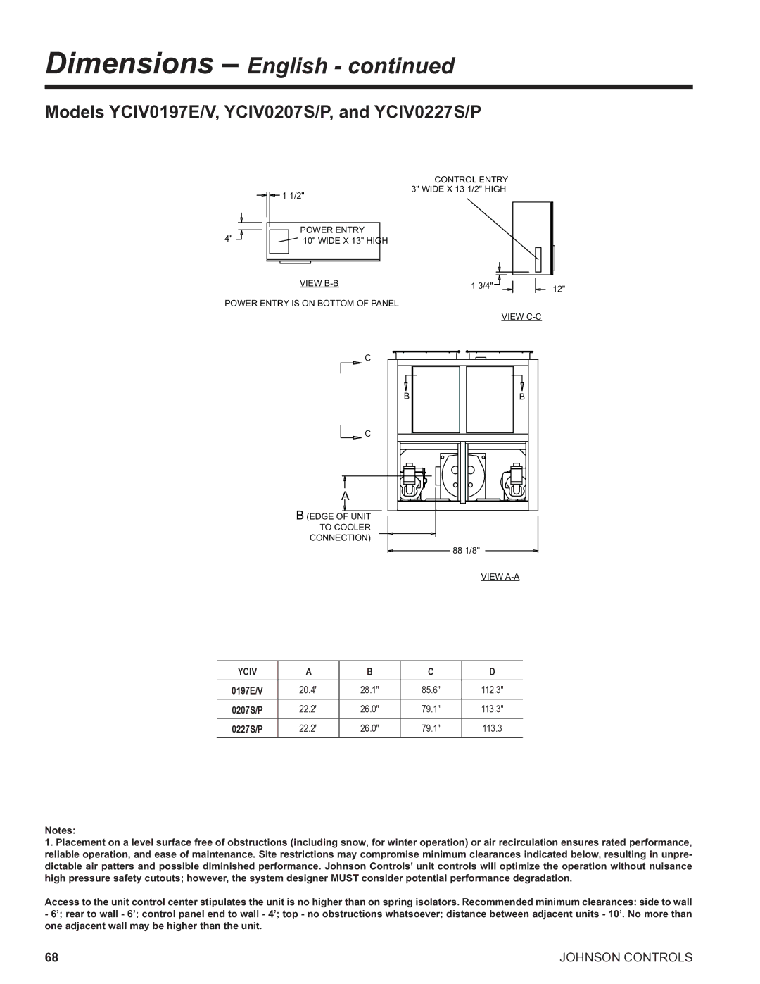
Models YCIV0197E/V, YCIV0207S/P, and YCIV0227S/P
20.4 28.1 85.6 112.3
22.2 26.0 79.1 113.3
22.2 26.0 79.1
274
88 1/8
Models YCIV0207E/V and YCIV0227E/V
20 3/8 28 1/8 Edge of Unit
Mounting Holes TYP
22 3/16
Models YCIV0247S/P, YCIV0247E/V, and YCIV0267S/P
Wide X 13 1/2 High
Mounting Holes TYP APPROX. Operating Weight Distributing LB
Models YCIV0267E/V, and YCIV0287S/P
Mounting Holes TYP Control Panel
Models YCIV0287E/V
Mounting Holes TYP
Models YCIV0307S/P
Water Outlet Water Inlet Rigging Holes
Models YCIV0327E/V and YCIV0357S/P
Control Panel Origin
Models YCIV0357E/V and YCIV0397S/P
View D-D Origin
Dimensions SI
YCIV0590E/V and YCIV0600S/P
485
442
Water Outlet Rigging Holes
Dimensions SI
YCIV0630E/V, YCIV0650S/P, YCIV0700E/V and YCIV0720S/P
2238
2032
Dimensions mm Unless Otherwise Noted
564
YCIV0760E/V, YCIV0770S/P, and YCIV0890S/P
518
Mounting Holes TYP Origin Panel
YCIV0800E/V and YCIV0830E/V
518
Water Outlet Mounting Holes TYP
YCIV0920S/P, YCIV0930E/V, and YCIV1000S/P
564
Rigging Holes Water Outlet Each Side 76 X
YCIV1050E/V and YCIV1070S/P
View A-A 305
Rigging Holes Water Outlet Water Inlet Each Side 76 X
YCIV1120E/V
Power Single Point with Terminal Block Origin Panel
YCIV1180S/P
Water Outlet Water Inlet Each Side 76 X
YCIV1220E/V and YCIV1340S/P
101
YCIV1380E/V and YCIV1500S/P
103
Isolator Locations x , y in. and Point Loads lbs
Isolator Locations English
Model
1753
1810
1775
2156
Isolator Locations English
High Efficiency English Model
1274
1839
2185
2493
Isolator Locations x , y mm and Point Loads kg
Isolator Locations SI
Standard Efficiency SI Model
566
572
675
730
High Efficiency SI Model
492
500
601
658
Isolator Details
ONE Inch Deflection Spring Isolator CROSS-REFERENCE
For Units with ALL Point Loads Less Thatn 1404 LBS 637 KG
For Units with ANY Point Load Above 1404 LBS 637 KG
Neoprene Isolator CROSS-REFERENCE
English MBD ND-C
ND-D
ND-DS
Size HCL HCW MBD
Isolator Details contd
English Size HCL HCW MBD
Intentionally Left Blank
OPT
Electrical Data 2 Comp Standard Efficiency
Yciv S/P
Yciv S/P
Two-Speed Cond. Fans
Electrical Data 2 Comp High Efficiency
Yciv E/V
Form 201.23-EG1 High Efficiency Yciv E/V
High Head/High Static Fans Two-Speed Cond. Fans
Electrical Data 3 Comp Standard Efficiency
FLA EA
STD Terminal Block OPT Circuit Breaker
Field Wiring Lugs
Form 201.23-EG1 System
Unit Short Circuit Field Wiring & Protection
Electrical Data 3 Comp High Efficiency
Withstand KA
High Head/High Static Fans
Lugs/ Phase
Fuse/Ckt
Electrical Notes
Power Wiring
Two COMPressor Wiring Diagram with Circuit Breaker
126
127
Typical Control Wiring Two Compressor
129
Typical Control Wiring Three Compressor
131
Application Data
Unit Location
Foundation
Chilled Liquid Piping
Guide Specifications
Part 1 General
Quality Assurance
Delivery and Handling
Compressors and Motors
Refrigerant Circuit Components
Power and Electrical Requirements
Controls
Accessories and Options
PRE-COATED FIN Condenser Coils
Part 3 Execution Installation
138
139
Form 201.23-EG1 Supersedes 201.23-EG1 File in ET2