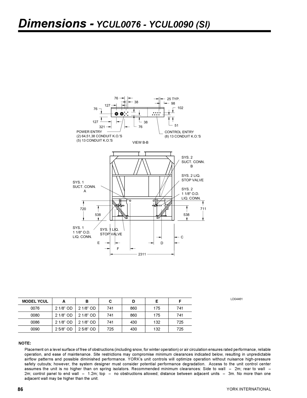
Dimensions - YCUL0076 - YCUL0090 (SI)
�� ![]()
![]()
![]() ��
��
��� ![]()
�� ![]()
��� | �� |
��� | �� |
�����������
���������������������������
�������
��
���
��
�������������
���������������������
���������������������
������
�����������
������������
��������
������
�����������
����������
�����������
����������
������
�����������
����������
��� |
| |
| ��� | |
������ | ����������� | |
����������� | ||
����������� | ||
���������� | ||
| ||
| � | |
| � |
����
���
���
![]() �
�
�
|
|
|
|
|
|
| LD04461 | |
MODEL YCUL | A | B | C | D | E | F | ||
| ||||||||
0076 | 2 1/8” OD | 2 1/8” OD | 741 | 860 | 175 | 741 |
| |
|
|
|
|
|
|
|
| |
0080 | 2 1/8” OD | 2 1/8” OD | 741 | 860 | 175 | 741 |
| |
|
|
|
|
|
|
|
| |
0086 | 2 1/8” OD | 2 1/8” OD | 741 | 430 | 132 | 725 |
| |
0090 | 2 5/8” OD | 2 5/8” OD | 725 | 430 | 132 | 725 |
| |
|
|
|
|
|
|
|
|
NOTE:
Placement on a level surface of free of obstructions (including snow, for winter operation) or air circulation ensures rated performance, reliable operation, and ease of maintenance. Site restrictions may compromise minimum clearances indicated below, resulting in unpredictable airflow patterns and possible diminished performance. YORK’s unit controls will optimize operation without nuisance
86 | YORK INTERNATIONAL |