
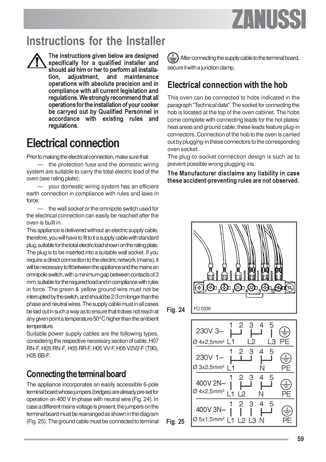
ZOU 592 specifications
The Zanussi ZOU 592 is a versatile built-in electric oven that combines modern design with advanced technology, catering to both amateur cooks and seasoned chefs. With its sleek appearance, this oven doesn’t just blend seamlessly into any kitchen décor but also offers a range of features that enhance cooking efficiency and effectiveness.One of the standout features of the Zanussi ZOU 592 is its multifunctional cooking options. The oven is equipped with several cooking modes, including conventional, fan-assisted, grill, and defrost settings. This flexibility allows users to choose the ideal cooking method for their dishes, ensuring perfect results every time. The fan-assisted mode, for example, distributes heat evenly throughout the oven, making it ideal for baking multiple trays of cookies or roasting large cuts of meat.
Another highlight of the Zanussi ZOU 592 is its digital control panel, which simplifies the cooking process. The intuitive display allows for easy selection of cooking functions and time settings, giving users precise control over their culinary creations. Additionally, the programmable timer ensures that meals can be cooked to perfection without the need for constant monitoring.
The oven's capacity is stately, providing ample space to accommodate large family meals or extravagant gatherings. The adjustable shelves can be easily rearranged, allowing users to maximize the interior space based on their cooking needs. Furthermore, the oven's robust build ensures durability, featuring high-quality materials that stand the test of time.
Energy efficiency is a focal point for many consumers today, and the Zanussi ZOU 592 delivers on this front as well. It boasts an impressive energy rating, helping to reduce electricity consumption without compromising performance. This means users can enjoy their culinary adventures with the added satisfaction of being environmentally conscious.
Cleaning the Zanussi ZOU 592 is a breeze, thanks to its easy-clean enamel interior. This innovative technology minimizes food residue and spills, making post-cooking cleanup straightforward. Additionally, the oven features a removable door that simplifies the cleaning process, ensuring that the appliance remains pristine after every use.
Overall, the Zanussi ZOU 592 is a well-designed oven that is packed with features tailored to meet the diverse needs of today’s home cooks. Its combination of multifunctionality, user-friendly controls, energy efficiency, and easy maintenance make it a worthwhile investment for any kitchen.