Basic Operation
Zoom and Focus Adjustment
Rotate the Zoom Lever to zoom in and out.
Rotate the Focus Ring to adjust the focus of the image.
![]() Zoom Lever
Zoom Lever
Focus Ring
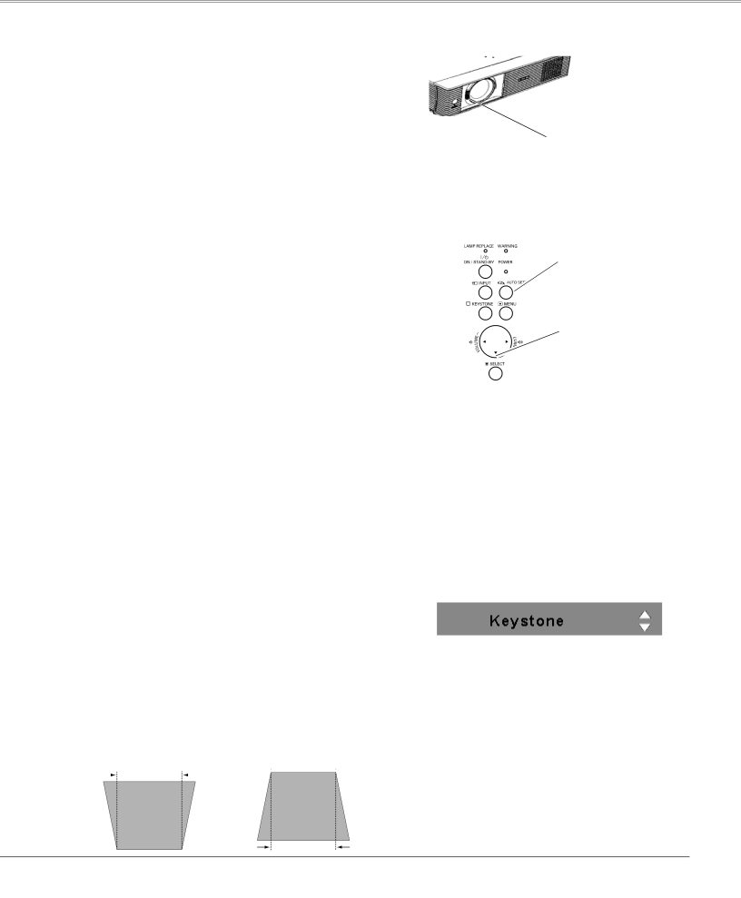
Auto Setup Function
Auto setup function is provided to automatically correct Keystone distortion according to the projector’s tilt and adjust the computer display parameters (Fine sync, Total dots, and Picture position) by just pressing the AUTO SETUP button on the top control. The operational setup for the Auto setup can be changed in the Setting menu. Refer to page 43 for the setting of the Auto setup function.
Notes:
•Auto Keystone corrects vertical distortion only; it does not correct horizontal distortion.
•Auto Keystone cannot work when Ceiling feature is set to “On” in the Setting menu (p.47).
•Perfect correction of the image distortion cannot be ensured with the Auto setup function. If the distortion cannot be corrected properly by pressing the AUTO SETUP button, adjust manually by pressing the KEYSTONE button on the top control or on the remote control or selecting Keystone in the Setting menu (p.44).
•Fine sync, Total dots, Horizontal and Vertical position of some computers cannot be fully adjusted with the Auto PC Adjustment function. When the image is not provided properly with this operation, manual adjustments are required
Top Control
AUTO SETUP button
![]() POINT▲▼buttons
POINT▲▼buttons
Keystone Correction
If a projected picture still has keystone distortion after pressing the AUTO SETUP button on the top control, correct the image manually as follows:
Press the KEYSTONE button on the top control or on the remote control. The Keystone dialog box appears. Use the Point ▲▼ buttons to correct keystone distortion. The keystone adjustment can be stored (p.44).
Reduce the upper width | Reduce the lower width | ||||
with the Point ▲ button. | with the Point ▼ button. | ||||
|
|
|
|
|
|
•The white arrows indicate that there is no correction.
•A red arrow indicates the direction of correction.
•An arrow disappears at the maximum correction.
•If you press the KEYSTONE button on the remote control or on the top control once more while the keystone dialog box is being displayed, the keystone adjustment will be canceled.
•The adjustable range is limited depending on the input signal.
23