Belkin PM11-EC/RAMA, PM11-EL/RAMA manual Hardware Installation 2 PS/2 Mouse and PS/2 Keyboard Ports

Page 26

2

Hardware Installation

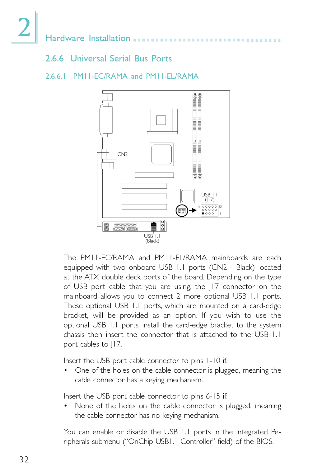
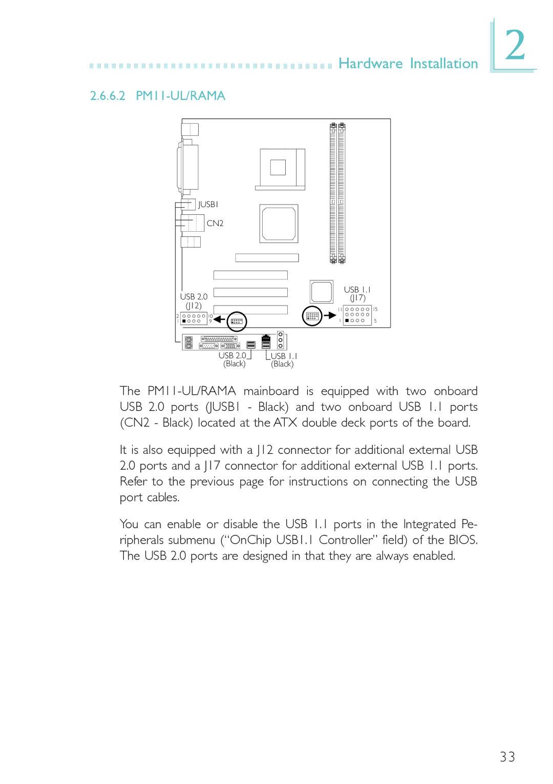
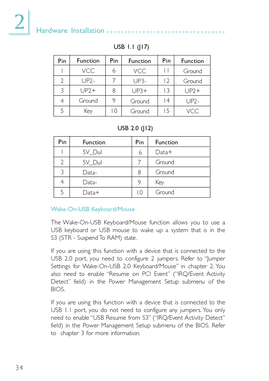
2.6.2 PS/2 Mouse and PS/2 Keyboard Ports

J2

PS/2 Mouse

PS/2 Keyboard

Mouse

(Green)

KB

(Purple)

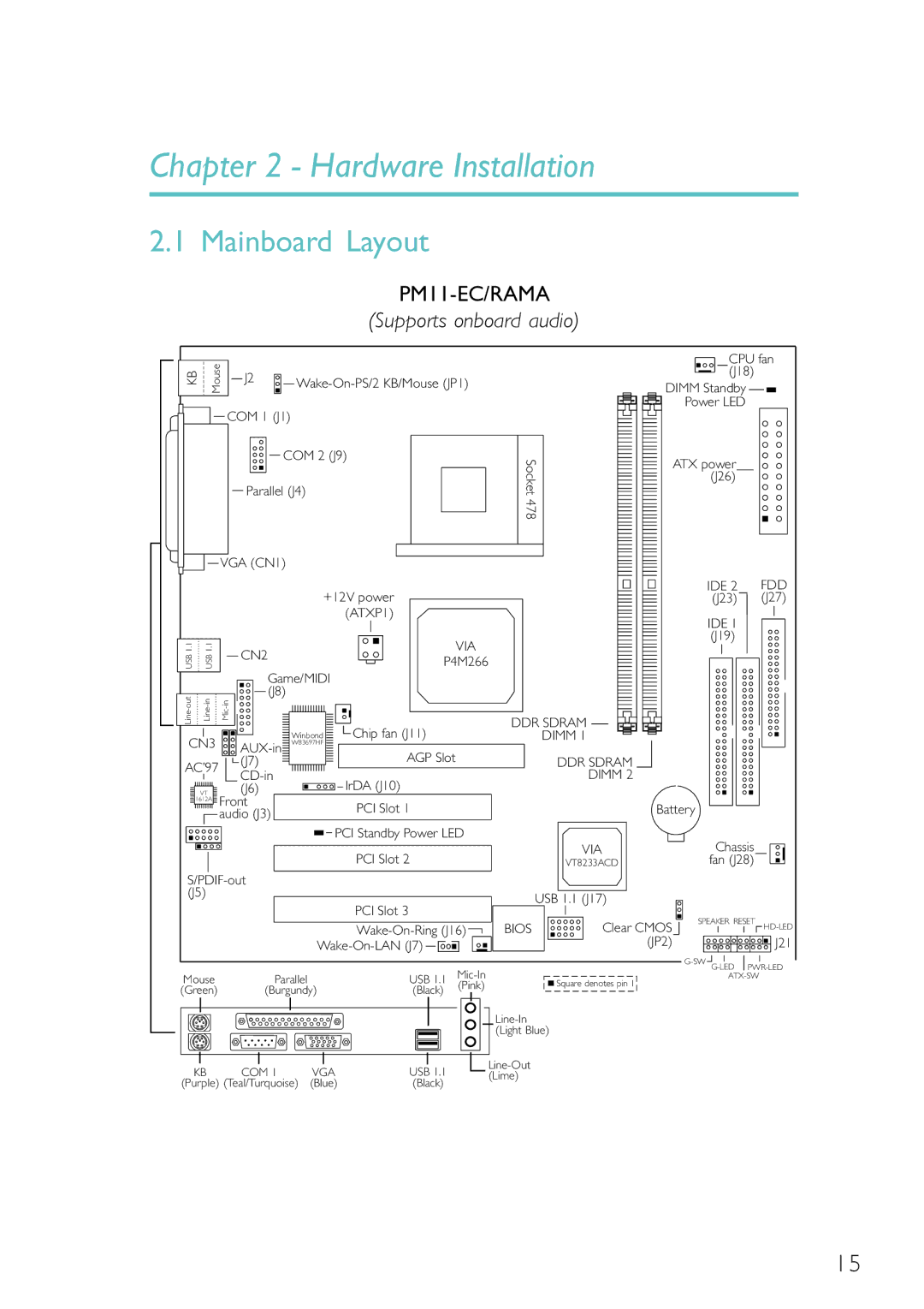
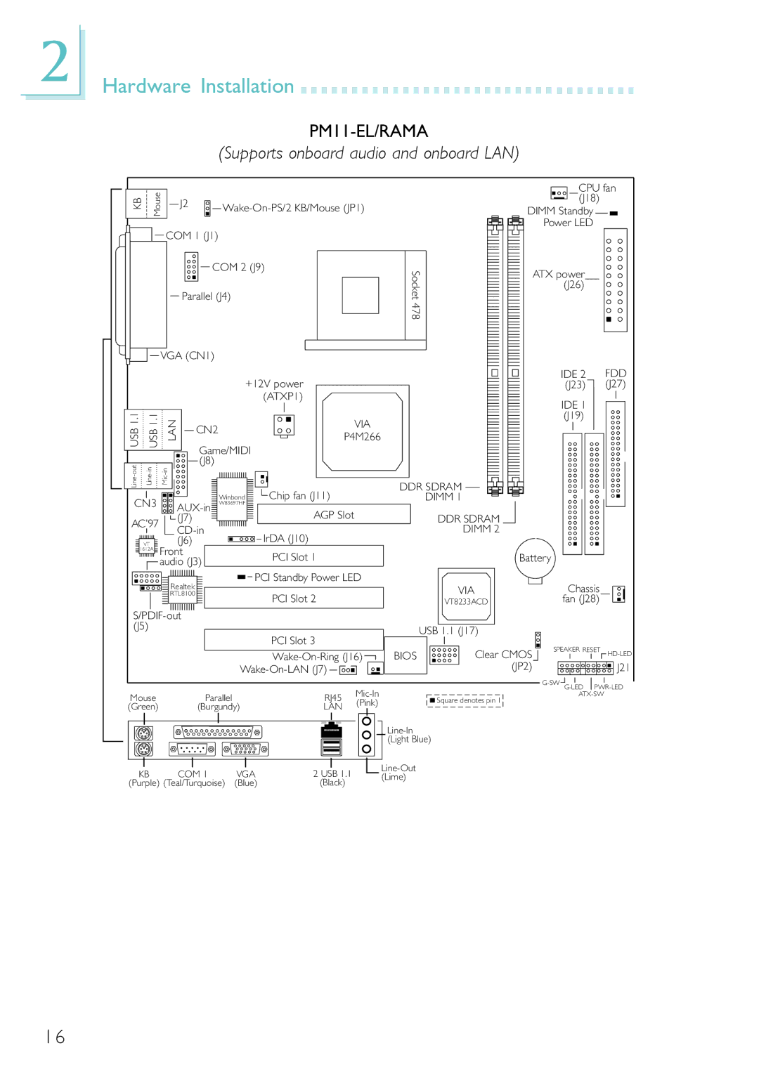
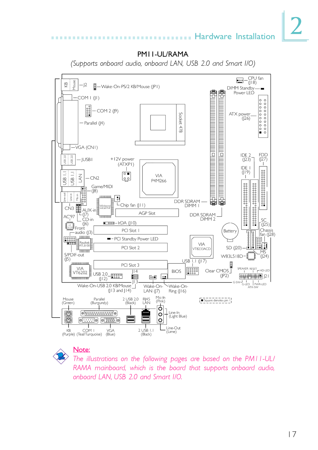
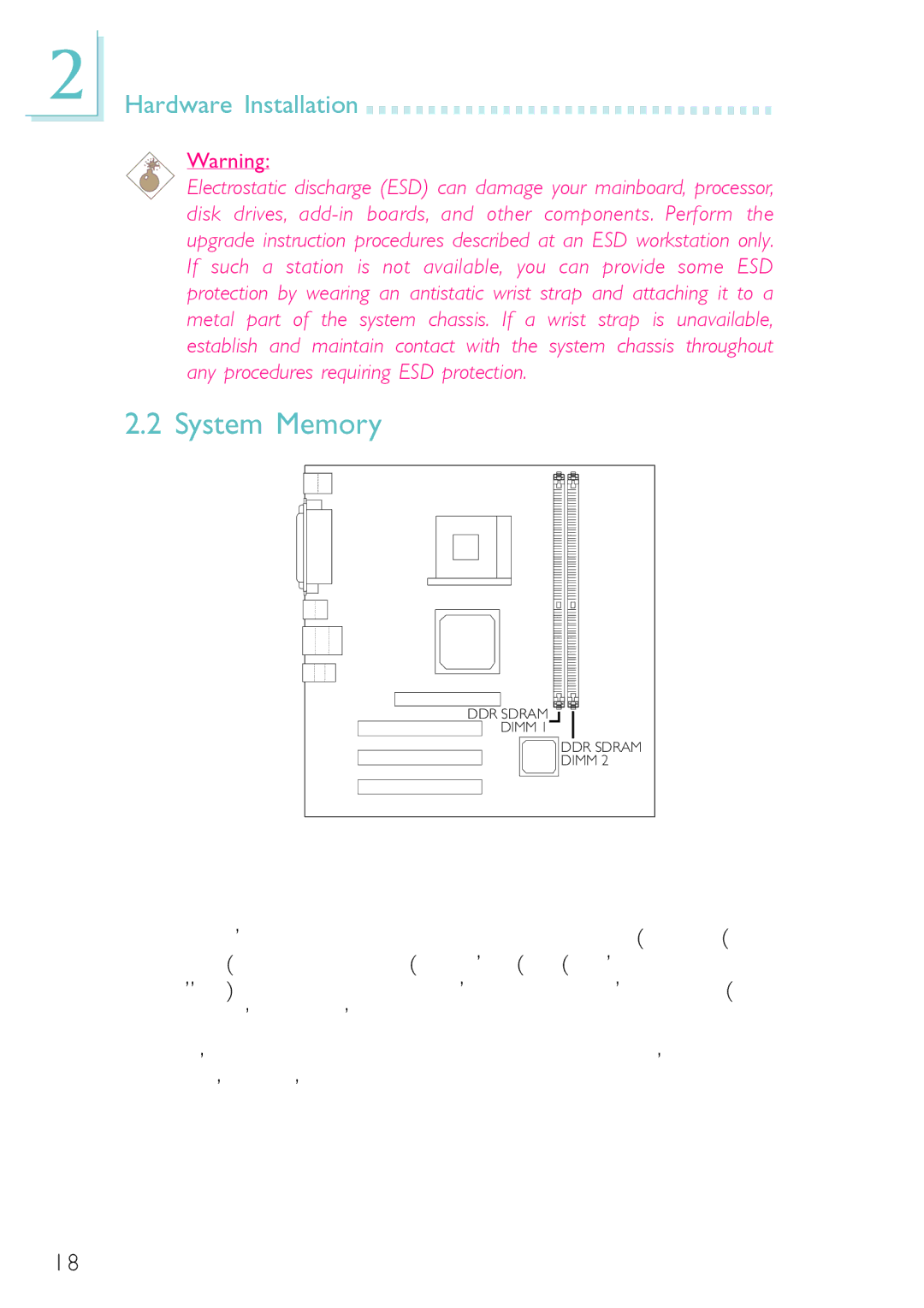
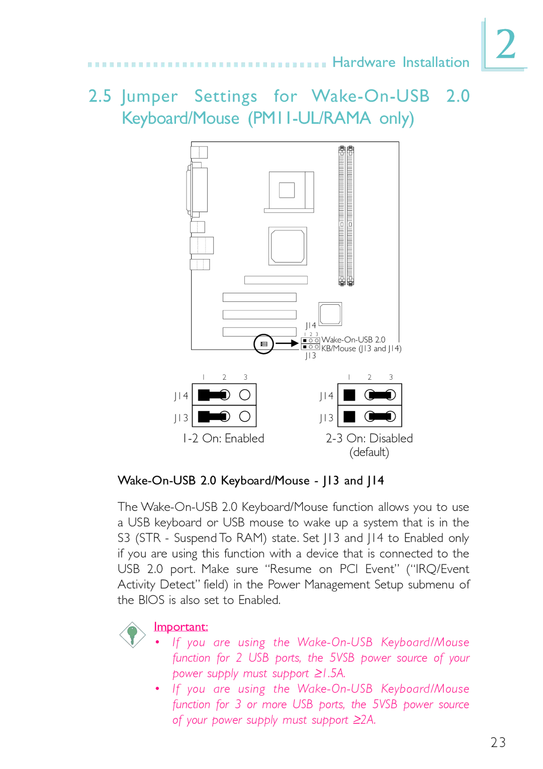
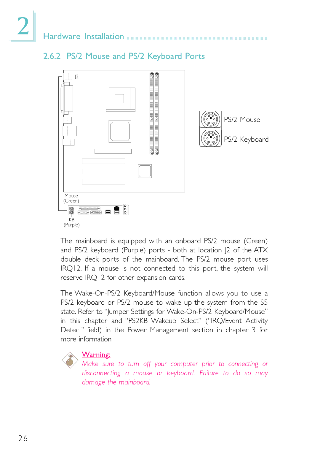
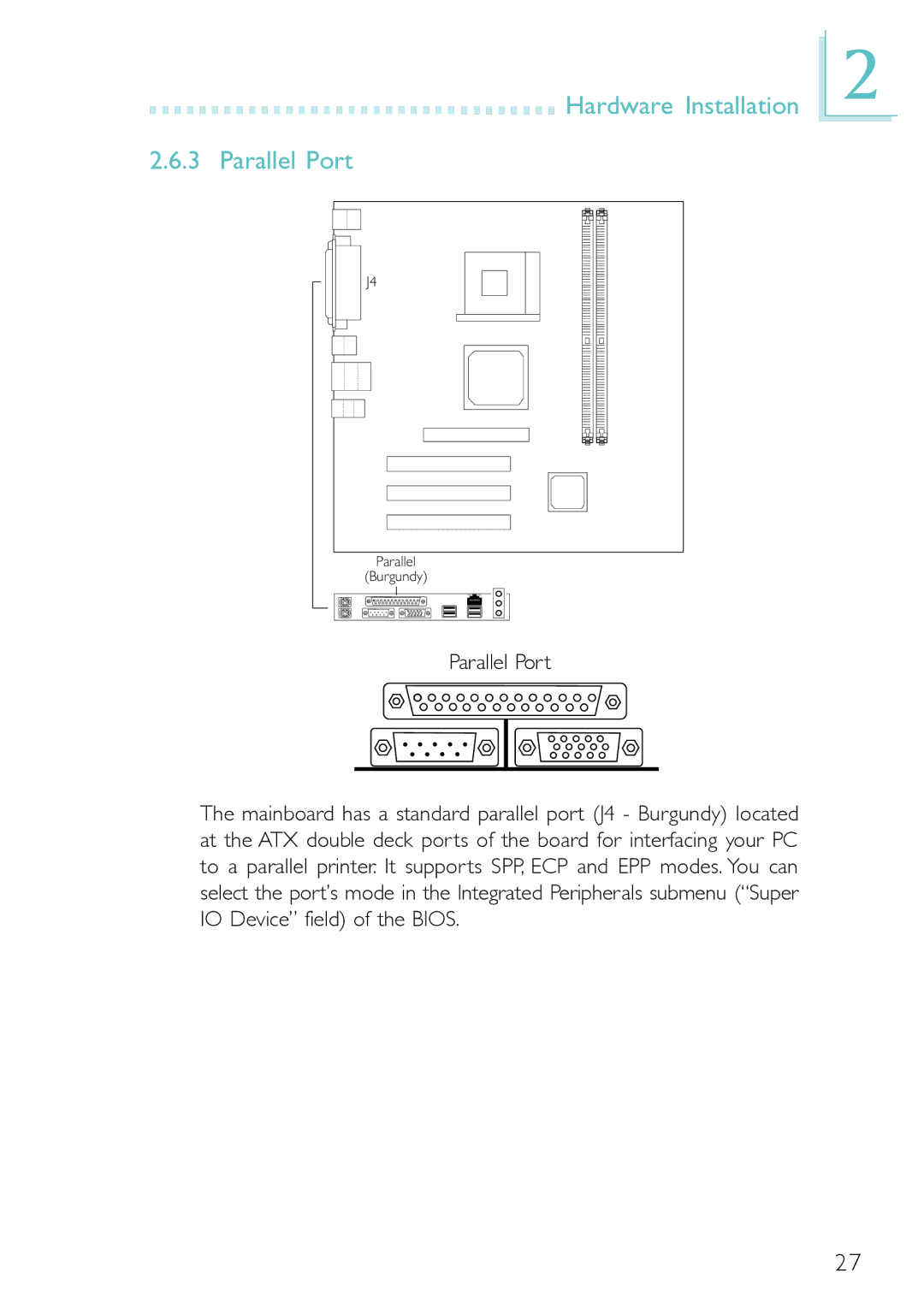
The mainboard is equipped with an onboard PS/2 mouse (Green) and PS/2 keyboard (Purple) ports - both at location J2 of the ATX double deck ports of the mainboard. The PS/2 mouse port uses IRQ12. If a mouse is not connected to this port, the system will reserve IRQ12 for other expansion cards.

The Wake-On-PS/2 Keyboard/Mouse function allows you to use a PS/2 keyboard or PS/2 mouse to wake up the system from the S5 state. Refer to “Jumper Settings for Wake-On-PS/2 Keyboard/Mouse” in this chapter and “PS2KB Wakeup Select” (“IRQ/Event Activity Detect” field) in the Power Management section in chapter 3 for more information.

Warning:

Make sure to turn off your computer prior to connecting or disconnecting a mouse or keyboard. Failure to do so may damage the mainboard.

26

Image 26
Contents PM11-EC/RAMA PM11-EL/RAMA PM11-UL/RAMA 55600206Copyright All Rights ReservedFCC and DOC Statement on Class B Mainboard Table of Contents Supported Softwares Appendix a Using the Suspend toAppendix C Troubleshooting FunctionChipset Features and SpecificationsFeatures ProcessorOnboard Graphics Features Onboard Audio FeaturesOnboard LAN Features PM11-EL/RAMA and PM11-UL/RAMA only IntroductionOnboard Integrated Media Reader Smart I/O PM11-UL/RAMA only ATX Double Deck Ports PC 99 color-coded connectorsConnectors USB Ports PCI Bus Master IDE ControllerIrDA Interface Intelligence Dual Function Power ButtonSystem Health Monitor Functions Desktop Management Interface DMIWake-On-PS/2 Keyboard/Mouse Wake-On-RingWake-On-LAN RTC Timer to Power-on the System Wake-On-USB Keyboard/MouseVirus Protection Package ChecklistAC Power Failure Recovery Hardware Installation Mainboard LayoutHardware Installation Supports onboard audio and onboard LANSupports onboard audio, onboard LAN, USB 2.0 and Smart I/O System Memory Hardware Installation Installing the DIM Module Jumper Settings for Clearing Cmos Data Clear Cmos Data Jumper JP2 If you encounter the followingHardware Installation Wake-On-PS/2 Keyboard/Mouse Jumper JP1 Jumper Settings for Wake-On-PS/2 Keyboard/MouseOn Disable VCC power Wake-On-USB 2.0 Keyboard/Mouse J13 and J14 Serial Ports Ports and ConnectorsConnecting the Serial Ports Serial PortHardware Installation Hardware Installation 2 PS/2 Mouse and PS/2 Keyboard Ports PS/2 Mouse PS/2 KeyboardHardware Installation Parallel Port Allows parallel port to operate Setting FunctionStandard Parallel Port One direction only RateHardware Installation Floppy Disk Drive Connector Connecting the Floppy Disk Drive CableHardware Installation IDE Disk Drive Connector Connecting the IDE Disk Drive CableAdding a Second IDE Disk Drive Hardware Installation Universal Serial Bus Ports 6.1 PM11-EC/RAMA and PM11-EL/RAMA6.2 PM11-UL/RAMA Function 5VDul Data+ Ground Key USB 1.1 J17 Pin FunctionUP2 RJ45 LAN Hardware Installation VGA Port VGA PortHardware Installation IrDA Connector Pin FunctionHardware Installation CPU Fan Connector Hardware Installation Chassis Fan Connector On/Off +12V SenseHardware Installation Chip Fan Connector Hardware Installation Game/MIDI Port Front Audio J3 Hardware Installation Audio JacksMic+ Ground Mic Power AuDVcc Avcc AuDROut AuDLOutFront Audio J3 Onboard Audio Jacks CN3Connect a microphone to the mic-in jack AUX-in and CD-in Hardware Installation Internal Audio ConnectorsLeft audio channel Ground Right audio channel Hardware Installation 16 S/PDIF-out Connector SpdifHardware Installation Smart I/O Connectors PM11-UL/RAMA only Optional Smart I/O Drive Secure Digital Memory Card Interface Smart Card Interface Pin FunctionMemory Stick Interface Hardware Installation Wake-On-LAN Connector +5VSBHardware Installation Wake-On-Ring Connector RI#PCI Standby Power LED Hardware Installation Dimm and PCI Standby Power LEDsDimm Standby Power LED Hardware Installation Power Connectors Ground +5V ATX Main Power Connector Pin Function 12V Ground +5V+12V +5V +12V Power Connector Pin Function Ground Hardware Installation Front Panel Connectors PWR-LED Power/Standby LED Basic Input/Output System Standard Cmos FeaturesWhen you press Del, the main menu screen will appear Time Award Bios Setup UtilityDate IDE HDD Auto DetectionCapacity Access ModeIDE Primary/Secondary Master/Slave Drive a and Drive BExtended Memory Halt OnBase Memory Total MemoryAward Bios Setup Utility Advanced Bios Features Virus WarningCPU L2 Cache ECC Checking Quick Power On Self TestCPU L1 & L2 Cache Swap Floppy DriveTypematic Rate Setting Boot Up Floppy SeekBoot Up NumLock Status Typematic Delay MsecOS Select for Dram 64MB Video Bios ShadowSecurity Option Small LogoEPA ShowCurrent FSB Frequency Award Bios Setup Utility Advanced Chipset FeaturesDram Clock/Drive Control Current Dram FrequencySdram CAS Latency Dram ClockDram Timing Bank InterleaveActive to Precharge Tras Dram Command RateAGP Mode Active to CMD TrcdCPU to PCI Write Buffer PCI Delay TransactionAGP Master 1 WS Read PCI Master 0 WS WriteVGA Share Memory Size Options are Enabled and DisabledVideo RAM Cacheable FB Address ConversionVIA OnChip IDE Device Award Bios Setup Utility Integrated PeripheralsIDE Prefetch Mode OnChip IDE Channel 0 and OnChip IDE ChannelOnboard LAN PM11-EL/RAMA and PM11-UL/RAMA only VIA OnChip PCI DeviceVIA-3058 AC97 Audio SC Port Address/IRQ PM11-UL/RAMA only Onboard FDC ControllerOnboard Serial Port 1 and Onboard Serial Port MS Port Address/IRQ PM11-UL/RAMA onlyUR2 Duplex Mode Uart Mode SelectIR Transmission Delay Use IR PinsECP Mode Use DMA Parallel Port ModeEPP Mode Select Game Port AddressOnChip USB1.1 Controller IDE HDD Block ModeOnboard LAN Boot ROM PM11-EL/RAMA and PM11-UL/RAMA only USB Keyboard SupportAcpi Suspend Type Award Bios Setup Utility Power Management SetupAcpi Function Suspend Mode Power Management OptionHDD Power Down Video Off OptionSoft-Off by Pwrbtn Run Vgabios if S3 ResumeModem Use IRQ PWR Lost Resume StateUSB Resume from S3 IRQ/Event Activity DetectPS2KB Wakeup Select PCI MasterResume On LAN/Ring Resume on AlarmResume on PCI Event IRQs Activity Monitoring Date of MonthResume Time hhmmss Reset Configuration Data Award Bios Setup Utility 6 PnP/PCI ConfigurationsPNP OS Installed Resources Controlled ByAssign IRQ for VGA IRQ ResourcesPCI/VGA Palette Snoop Assign IRQ for USBPCI Slot 1 Use IRQ to PCI Slot 3 Use IRQ These fields show the voltage of the processor Award Bios Setup Utility PC Health StatusCPU Warning Temperature +3.3V, +5V, +12V, -12V, -5V, Vbatv and 5VSBV Auto Detect PCI/DIMM Clk Award Bios Setup Utility Frequency/Voltage ControlCPU Clock Spread SpectrumCPU Clock Ratio This field is used to select the CPU’s frequency ratioAward Bios Setup Utility Load Fail-Safe Defaults Load Optimized DefaultsAward Bios Setup Utility Set Supervisor Password Set User PasswordExit Without Saving Updating the BiosAward Bios Setup Utility Save & Exit Setup Desktop Management Interface DMI Running the DMI UtilitySupported Software Using the DMI Utility Edit DMISave DMI File Supported Software Add DMILoad DMI File Supported Software VIA Service PackHardware Monitor VIA Service Pack Installation Notes Audio Drivers and Software Applications Winbond Smart I/O Drivers PM11-UL/ Rama only Graphics DriversVIA USB 2.0 Driver PM11-UL/RAMA only Drivers and Utilities Installation Notes Microsoft DirectX 8.1 DriverAppendix a Using the Suspend to RAM Function Using the Suspend to RAM FunctionUsing the Suspend to RAM Function 101 102 Post Beep Error MessagesCmos battery is no longer functional. It should be replaced System Error Message Troubleshooting Checklist Monitor/DisplayFloppy Drive TroubleshootingPower Supply Troubleshooting Hard Drive Hard disk failureMainboard Troubleshooting Serial PortKeyboard