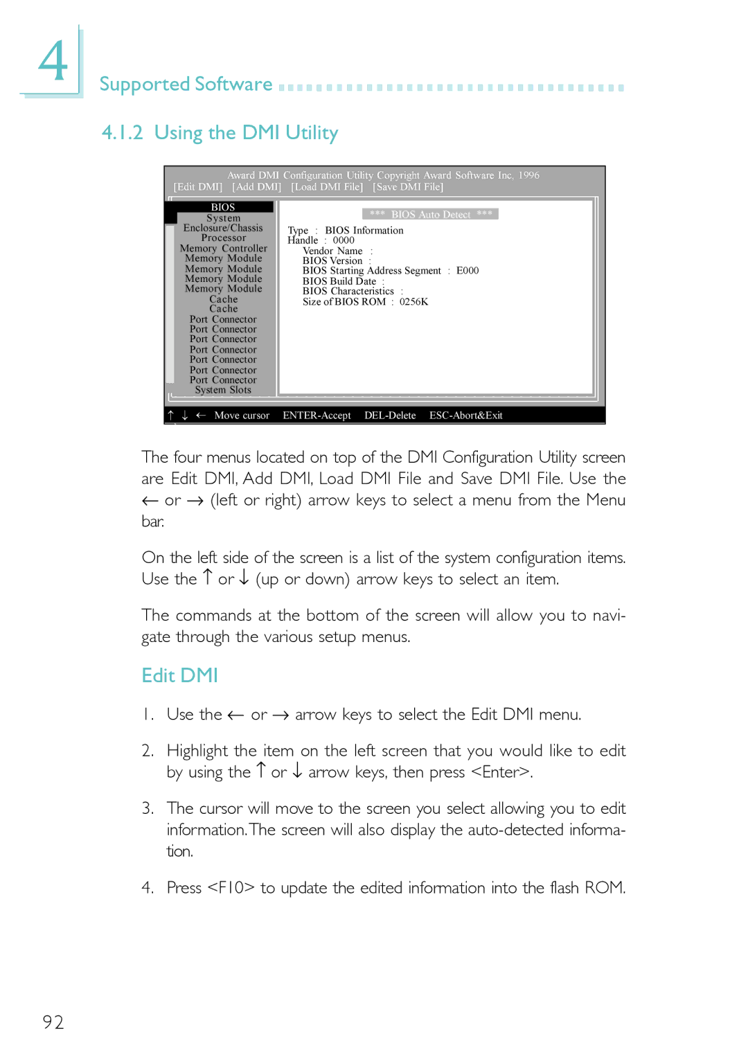
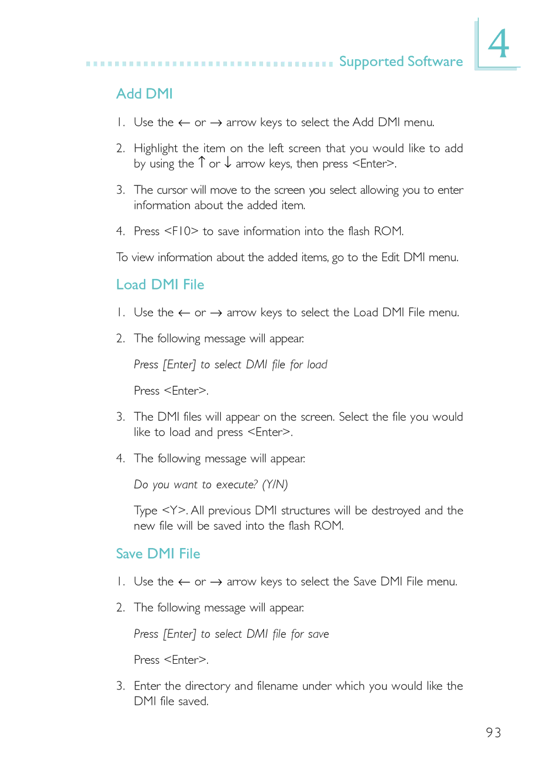
Belkin PM11-UL/RAMA, PM11-EL/RAMA manual Desktop Management Interface DMI, Running the DMI Utility

Page 91

Chapter 4 - Supported Software

4.1 Desktop Management Interface (DMI)

The mainboard comes with a DMI built into the BIOS. DMI, along with the appropriately networked software, is designed to make inventory, maintenance and troubleshooting of computer systems easier. With DMI, a network administrator or MIS engineer can remotely access some information about a particular computer system without physically going to it. Quite often a service call may be unnecessary as the problem can be solved remotely.

The DMI utility in the BIOS automatically records various information about your system configuration. Information about the type and speed of CPU, type and amount of memory for each memory slot, BIOS revision level, types of add-in PCI boards and components, certain re- vision numbers of hardware installed, etc. are automatically detected and stored in the DMI pool, which is a part of the mainboard's Plug and Play BIOS. Additional information, such as ISA based peripherals, which may not be automatically detected, can be manually recorded in the DMI pool by using the Add DMI menu. The DMI pool data is then verified or updated whenever the system hardware or setup is altered.

4.1.1 Running the DMI Utility

To run the DMI utility, type: DMICFG.EXE.

The DMI utility must run in real mode with at least 180K of base memory. Memory managers like HIMEM.SYS (required by Windows) must not be installed. You may do this by using one of the 3 meth- ods listed below.

1.Boot up from a system diskette without the AUTOEXEC.BAT and CONFIG.SYS files,

2.“REM” HIMEM.SYS in the CONFIG.SYS, or

3.Press <F5> during bootup to bypass your AUTOEXEC.BAT and CONFIG.SYS files.

91
Image 91
Contents 55600206 PM11-EC/RAMA PM11-EL/RAMA PM11-UL/RAMAAll Rights Reserved CopyrightFCC and DOC Statement on Class B Mainboard Table of Contents Function Appendix a Using the Suspend toAppendix C Troubleshooting Supported SoftwaresProcessor Features and SpecificationsFeatures ChipsetIntroduction Onboard Audio FeaturesOnboard LAN Features PM11-EL/RAMA and PM11-UL/RAMA only Onboard Graphics FeaturesConnectors ATX Double Deck Ports PC 99 color-coded connectorsOnboard Integrated Media Reader Smart I/O PM11-UL/RAMA only IrDA Interface PCI Bus Master IDE ControllerUSB Ports Desktop Management Interface DMI Dual Function Power ButtonSystem Health Monitor Functions IntelligenceWake-On-LAN Wake-On-RingWake-On-PS/2 Keyboard/Mouse Wake-On-USB Keyboard/Mouse RTC Timer to Power-on the SystemAC Power Failure Recovery Package ChecklistVirus Protection Mainboard Layout Hardware InstallationSupports onboard audio and onboard LAN Hardware InstallationSupports onboard audio, onboard LAN, USB 2.0 and Smart I/O System Memory Hardware Installation Installing the DIM Module Clear Cmos Data Jumper JP2 If you encounter the following Jumper Settings for Clearing Cmos DataHardware Installation On Disable VCC power Jumper Settings for Wake-On-PS/2 Keyboard/MouseWake-On-PS/2 Keyboard/Mouse Jumper JP1 Wake-On-USB 2.0 Keyboard/Mouse J13 and J14 Serial Port Ports and ConnectorsConnecting the Serial Ports Serial PortsHardware Installation PS/2 Mouse PS/2 Keyboard Hardware Installation 2 PS/2 Mouse and PS/2 Keyboard PortsHardware Installation Parallel Port Rate Setting FunctionStandard Parallel Port One direction only Allows parallel port to operateConnecting the Floppy Disk Drive Cable Hardware Installation Floppy Disk Drive ConnectorConnecting the IDE Disk Drive Cable Hardware Installation IDE Disk Drive ConnectorAdding a Second IDE Disk Drive 6.1 PM11-EC/RAMA and PM11-EL/RAMA Hardware Installation Universal Serial Bus Ports6.2 PM11-UL/RAMA UP2 USB 1.1 J17 Pin FunctionFunction 5VDul Data+ Ground Key RJ45 LAN VGA Port Hardware Installation VGA PortPin Function Hardware Installation IrDA ConnectorHardware Installation CPU Fan Connector On/Off +12V Sense Hardware Installation Chassis Fan ConnectorHardware Installation Chip Fan Connector Hardware Installation Game/MIDI Port AuDLOut Hardware Installation Audio JacksMic+ Ground Mic Power AuDVcc Avcc AuDROut Front Audio J3Connect a microphone to the mic-in jack Onboard Audio Jacks CN3Front Audio J3 Left audio channel Ground Right audio channel Hardware Installation Internal Audio ConnectorsAUX-in and CD-in Spdif Hardware Installation 16 S/PDIF-out ConnectorHardware Installation Smart I/O Connectors PM11-UL/RAMA only Optional Smart I/O Drive Memory Stick Interface Smart Card Interface Pin FunctionSecure Digital Memory Card Interface +5VSB Hardware Installation Wake-On-LAN ConnectorRI# Hardware Installation Wake-On-Ring ConnectorDimm Standby Power LED Hardware Installation Dimm and PCI Standby Power LEDsPCI Standby Power LED Hardware Installation Power Connectors +12V +5V +12V Power Connector Pin Function Ground ATX Main Power Connector Pin Function 12V Ground +5VGround +5V Hardware Installation Front Panel Connectors PWR-LED Power/Standby LED When you press Del, the main menu screen will appear Standard Cmos FeaturesBasic Input/Output System IDE HDD Auto Detection Award Bios Setup UtilityDate TimeDrive a and Drive B Access ModeIDE Primary/Secondary Master/Slave CapacityTotal Memory Halt OnBase Memory Extended MemoryVirus Warning Award Bios Setup Utility Advanced Bios FeaturesSwap Floppy Drive Quick Power On Self TestCPU L1 & L2 Cache CPU L2 Cache ECC CheckingTypematic Delay Msec Boot Up Floppy SeekBoot Up NumLock Status Typematic Rate SettingSmall LogoEPA Show Video Bios ShadowSecurity Option OS Select for Dram 64MBCurrent Dram Frequency Award Bios Setup Utility Advanced Chipset FeaturesDram Clock/Drive Control Current FSB FrequencyBank Interleave Dram ClockDram Timing Sdram CAS LatencyActive to CMD Trcd Dram Command RateAGP Mode Active to Precharge TrasPCI Master 0 WS Write PCI Delay TransactionAGP Master 1 WS Read CPU to PCI Write BufferFB Address Conversion Options are Enabled and DisabledVideo RAM Cacheable VGA Share Memory SizeOnChip IDE Channel 0 and OnChip IDE Channel Award Bios Setup Utility Integrated PeripheralsIDE Prefetch Mode VIA OnChip IDE DeviceVIA-3058 AC97 Audio VIA OnChip PCI DeviceOnboard LAN PM11-EL/RAMA and PM11-UL/RAMA only MS Port Address/IRQ PM11-UL/RAMA only Onboard FDC ControllerOnboard Serial Port 1 and Onboard Serial Port SC Port Address/IRQ PM11-UL/RAMA onlyUse IR Pins Uart Mode SelectIR Transmission Delay UR2 Duplex ModeGame Port Address Parallel Port ModeEPP Mode Select ECP Mode Use DMAUSB Keyboard Support IDE HDD Block ModeOnboard LAN Boot ROM PM11-EL/RAMA and PM11-UL/RAMA only OnChip USB1.1 ControllerAcpi Function Award Bios Setup Utility Power Management SetupAcpi Suspend Type Video Off Option Power Management OptionHDD Power Down Suspend ModePWR Lost Resume State Run Vgabios if S3 ResumeModem Use IRQ Soft-Off by PwrbtnPCI Master IRQ/Event Activity DetectPS2KB Wakeup Select USB Resume from S3Resume on PCI Event Resume on AlarmResume On LAN/Ring Resume Time hhmmss Date of MonthIRQs Activity Monitoring Resources Controlled By Award Bios Setup Utility 6 PnP/PCI ConfigurationsPNP OS Installed Reset Configuration DataAssign IRQ for USB IRQ ResourcesPCI/VGA Palette Snoop Assign IRQ for VGAPCI Slot 1 Use IRQ to PCI Slot 3 Use IRQ CPU Warning Temperature Award Bios Setup Utility PC Health StatusThese fields show the voltage of the processor +3.3V, +5V, +12V, -12V, -5V, Vbatv and 5VSBV Spread Spectrum Award Bios Setup Utility Frequency/Voltage ControlCPU Clock Auto Detect PCI/DIMM ClkThis field is used to select the CPU’s frequency ratio CPU Clock RatioLoad Optimized Defaults Award Bios Setup Utility Load Fail-Safe DefaultsSet User Password Award Bios Setup Utility Set Supervisor PasswordAward Bios Setup Utility Save & Exit Setup Updating the BiosExit Without Saving Running the DMI Utility Desktop Management Interface DMIEdit DMI Supported Software Using the DMI UtilityLoad DMI File Supported Software Add DMISave DMI File Hardware Monitor VIA Service PackSupported Software VIA Service Pack Installation Notes Audio Drivers and Software Applications VIA USB 2.0 Driver PM11-UL/RAMA only Graphics DriversWinbond Smart I/O Drivers PM11-UL/ Rama only Microsoft DirectX 8.1 Driver Drivers and Utilities Installation NotesUsing the Suspend to RAM Function Appendix a Using the Suspend to RAM FunctionUsing the Suspend to RAM Function 101 102 Cmos battery is no longer functional. It should be replaced Error MessagesPost Beep System Error Message Monitor/Display Troubleshooting ChecklistPower Supply TroubleshootingFloppy Drive Hard disk failure Troubleshooting Hard DriveKeyboard Troubleshooting Serial PortMainboard