Fujitsu TX150 S3 manual Accessible drives, Installing an accessible 5.25-inch drive

Page 33

6 Accessible drives

VCAUTION!

Observe the safety instructions in the chapter “Safety notes” on page 7 et seqq. .

Three 5.25-inch bays are available for accessible drives. The top side bay is already equipped with a CD/DVD-ROM drive. The two lower bays can also be used to install a hard disks extension box.

6.1Installing an accessible 5.25-inch drive

The 5.25-inch drives available are magnetic tape drives, CD/DVD-ROM drives and CD/DVD-ROM burners. These drives can be installed in the two free 5.25- inch bays.

ÊOpen the server and remove the front cover or rack front cover as described in the chapter “Preparation” on page 13 et seqq. .

INew 5.25-inch drives are supplied without EasyClick rails. Before installing a new drive you must therefore remove the EasyClick rails from the dummy cover and mount the EasyClick rails on the new drive.


1

1

2

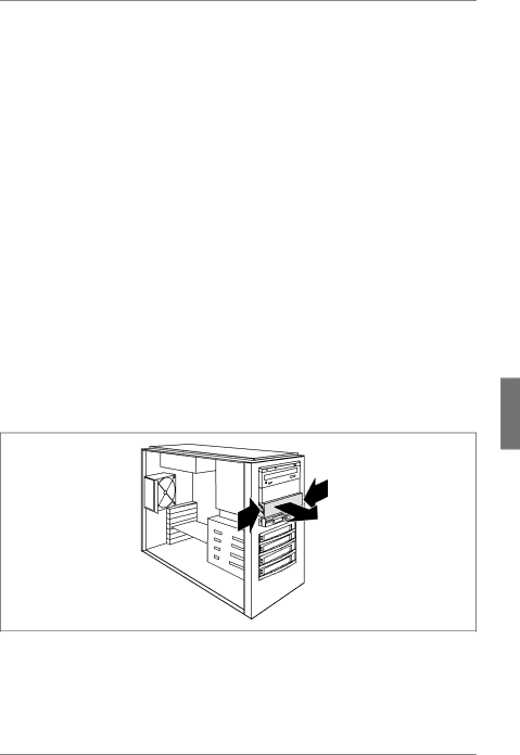
Figure 15: Removing the dummy cover

ÊPress the two metal tongues of the EasyClick rails inward (1) until the locking mechanism is released.

ÊRemove the dummy cover from the bay (2).

U41604-Z156-1-76

Options Guide

25

Image 33
Contents Primergy TX150 S3 Server System Comments… Suggestions… Corrections… Copyright and TrademarksCertified documentation according to DIN EN ISO Page Page Page Page Contents Contents Overview of the documentation IntroductionConcept and target groups Additional documentation about the serverExtensions and conversions Extensions and conversionsFurther sources of information Extension of the main memoryIntroduction Additional accessible drivesHard disks extension box Additional controllers in the PCI slotsNotational conventions Conversion standard power supply to hot-plug power supplyNotational conventions Conversion of the floorstand model to a rack modelProcedure Page Before operating the device Safety notesSafety notes Installation and operation Safety notes Safety notes Batteries Never remove parts of the CD-/DVD-ROM drive assembly Safety notes Modules with electrostatic-sensitive components Preparation Floorstand modelOpening the server Floorstand model Removing the front coverPreparation Removing the hard disk coverRack model Rack modelRack model Loosening the screws Removing the rack front cover Removing the rack front coverPage Equipping rules Main memoryExtending/replacing the main memory Extending/replacing the main memoryInserting a memory module Main memoryPage Installing an accessible 5.25-inch drive Accessible drivesAttaching the EasyClick rails DVD-ROM burner Installing an accessible 5.25-inch driveAccessible drives Attaching the EasyClick rails magnetic tape drive VXA-2 Installing the hard disks extension box Attaching the EasyClick rails Installing the hard disks extension boxPCIe Slot PCI Slot Controller in the PCI slotsInstalling a controller Installing a controllerController in the PCI slots Installing a controllerPCI slot assembling PCI slot assemblingRemoteView components RemoteView Service Board S2 LPRemoteView components RSB S2 LP RemoteView Service Board S2 LP External Scsi interface Installing the external Scsi interfacePage Conversion standard PS to hot- plug PS Taking out the standard power supply Installing the Power backplane in the PS cage Installing the PS cage Fastening the PS cage in the housing Fastening the PS cage at the rear side Inserting the power supply module Locking the power supply module Installing the dummy cover Mounting the anti-tilt bracket Fastening the anti-tilt bracket Page Removing the anti-tilt bracket Converting from the floorstand model to the rack modelRight-hand side cover and the top cover build one part Removing the rubber feet Installing the operating panel module Converting from the floorstand model to the rack model Page Attaching the hard disk cover CompletionAttaching the front cover Attaching the front coverCompletion Closing the serverAttaching the plastic front cover Attaching the rack front coverAttaching the rack front cover Attaching the top cover Installing the server in a rack cabinet Fastening the server in the rack cabinet Rack model CompletionCabling AppendixScsi version Channel Scsi version with onboard Scsi controllerScsi RAID CablingIDE/FD Data Cable prefix T26139 Controller Sata versionPage Abbreviations Abbreviations HDD MRL SCA Page Related publications Related Publications Index Page Comments Suggestions Corrections Page Comments Suggestions Corrections Page Hinweise zum vorliegenden Dokument Information on this document