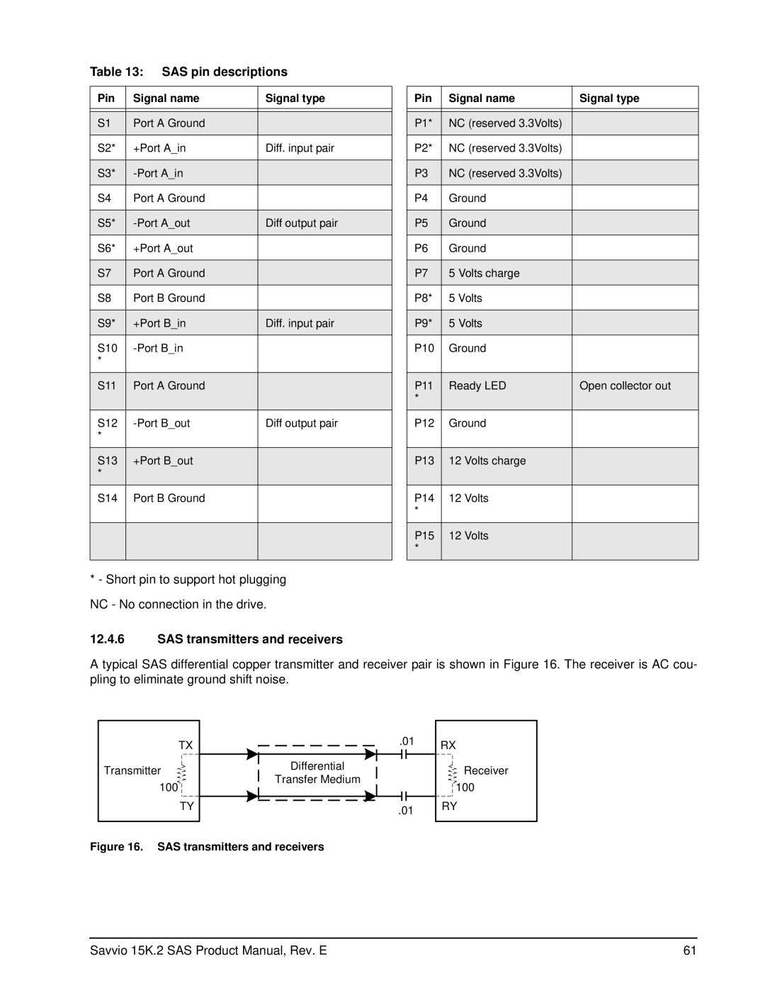
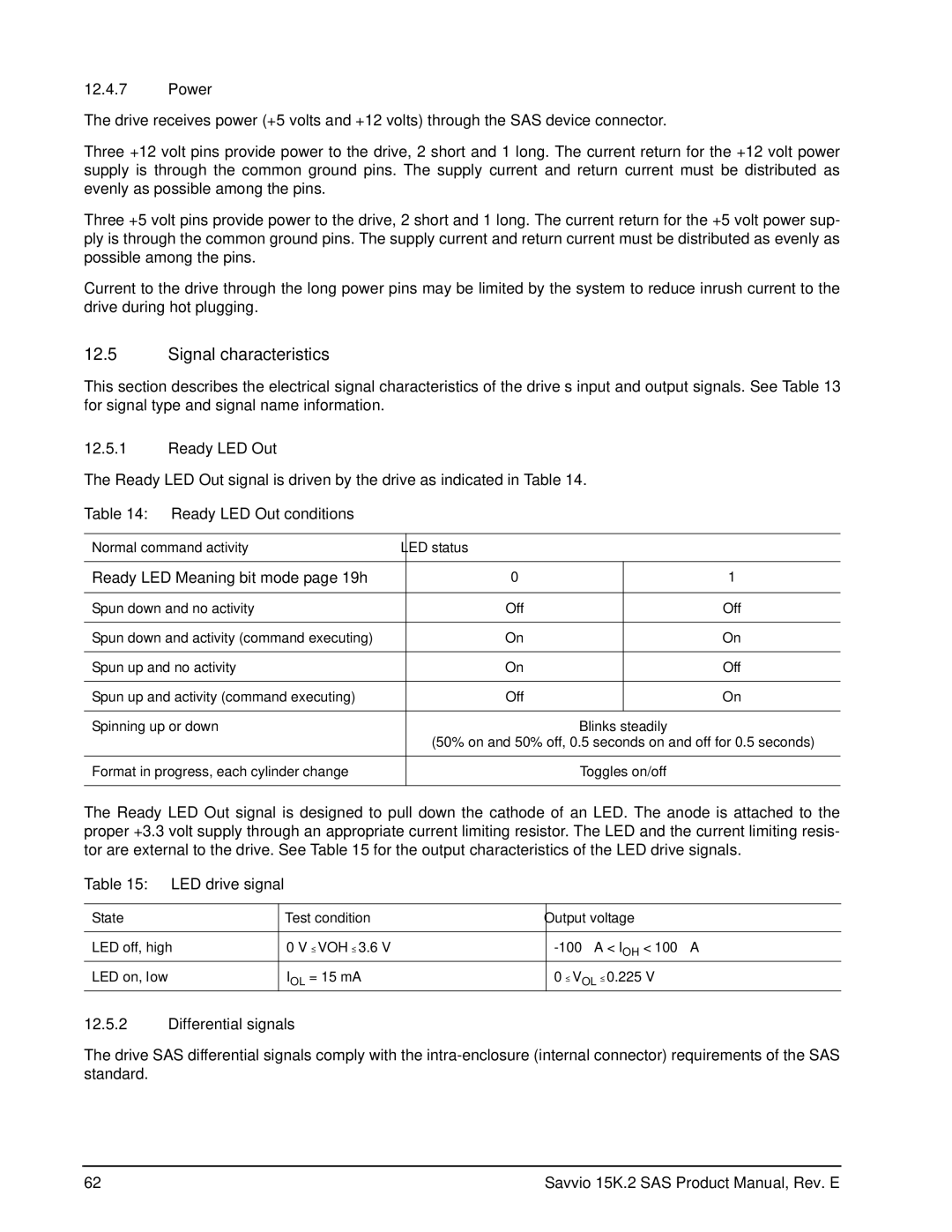
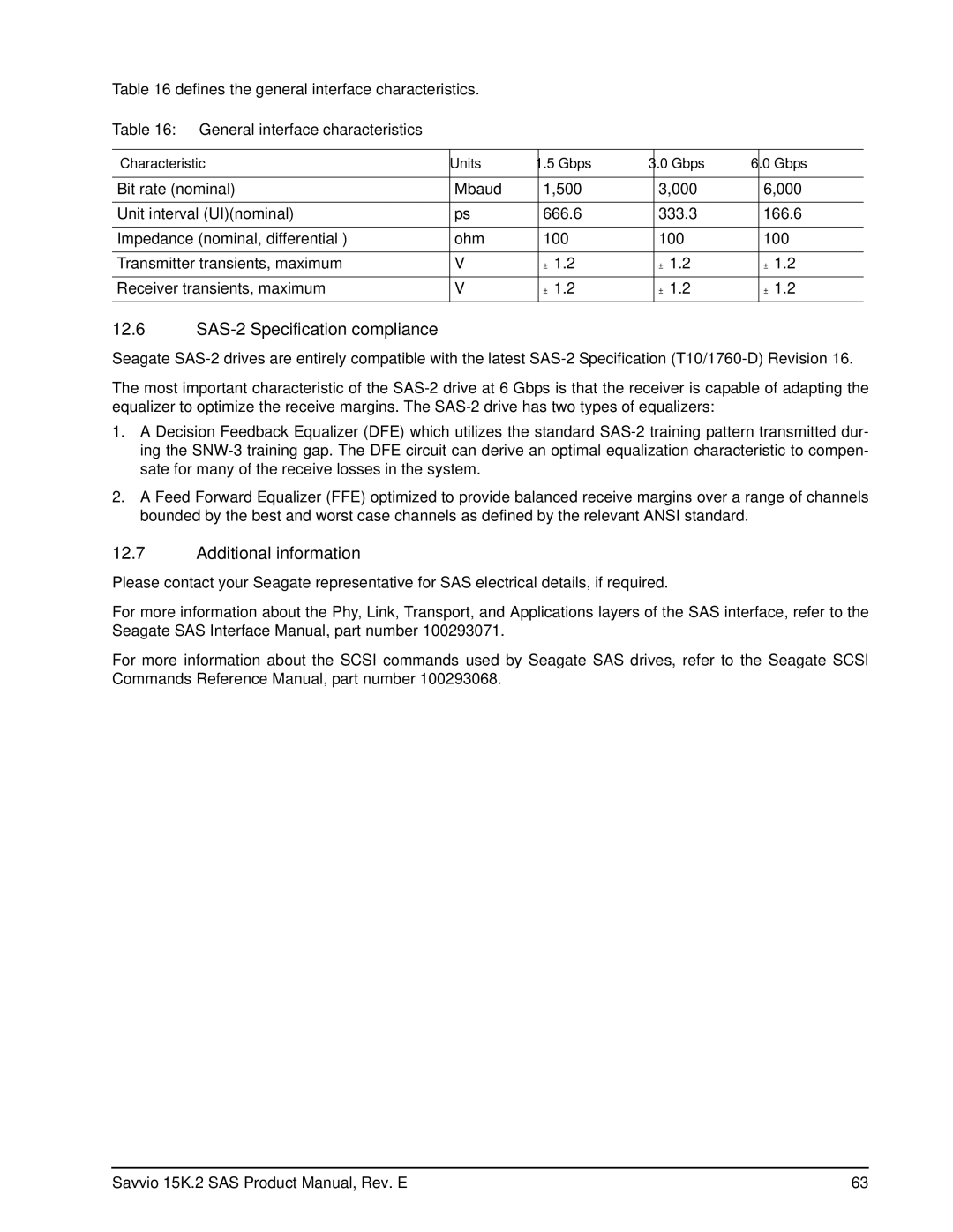
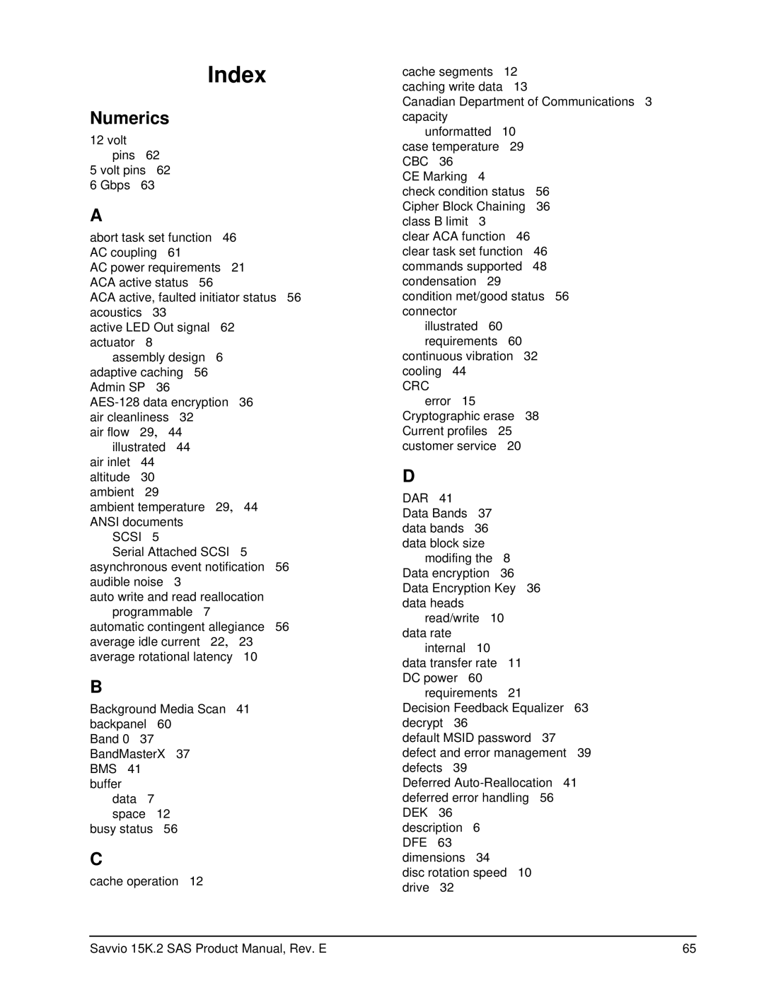
Seagate ST9146852SS, ST973452SS, ST973352SS, ST973252SS, ST9146752SS manual Signal characteristics

Page 70

12.4.7Power

The drive receives power (+5 volts and +12 volts) through the SAS device connector.

Three +12 volt pins provide power to the drive, 2 short and 1 long. The current return for the +12 volt power supply is through the common ground pins. The supply current and return current must be distributed as evenly as possible among the pins.

Three +5 volt pins provide power to the drive, 2 short and 1 long. The current return for the +5 volt power sup- ply is through the common ground pins. The supply current and return current must be distributed as evenly as possible among the pins.

Current to the drive through the long power pins may be limited by the system to reduce inrush current to the drive during hot plugging.

12.5Signal characteristics

This section describes the electrical signal characteristics of the drive’s input and output signals. See Table 13 for signal type and signal name information.

12.5.1Ready LED Out

The Ready LED Out signal is driven by the drive as indicated in Table 14.

Table 14: Ready LED Out conditions

Normal command activity

LED status


Ready LED Meaning bit mode page 19h

0


1


Spun down and no activity

Off


Off


Spun down and activity (command executing)

On


On


Spun up and no activity

On


Off


Spun up and activity (command executing)

Off


On


Spinning up or down


Blinks steadily


(50% on and 50% off, 0.5 seconds on and off for 0.5 seconds)


Format in progress, each cylinder change


Toggles on/off


The Ready LED Out signal is designed to pull down the cathode of an LED. The anode is attached to the proper +3.3 volt supply through an appropriate current limiting resistor. The LED and the current limiting resis- tor are external to the drive. See Table 15 for the output characteristics of the LED drive signals.

Table 15:

LED drive signal


State


Test condition

Output voltage


LED off, high


0 V VOH 3.6 V

-100 µA < IOH < 100 µA

LED on, low


IOL = 15 mA

0 VOL 0.225 V

12.5.2Differential signals

The drive SAS differential signals comply with the intra-enclosure (internal connector) requirements of the SAS standard.

62

Savvio 15K.2 SAS Product Manual, Rev. E

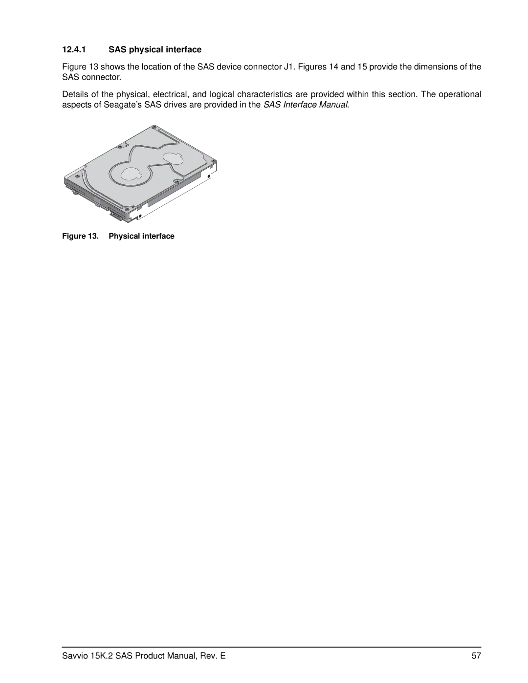
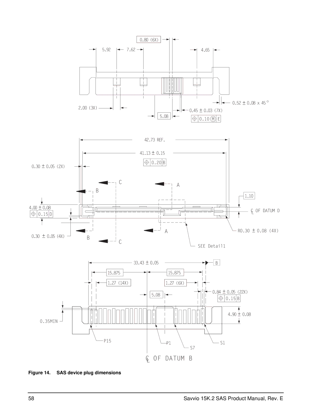
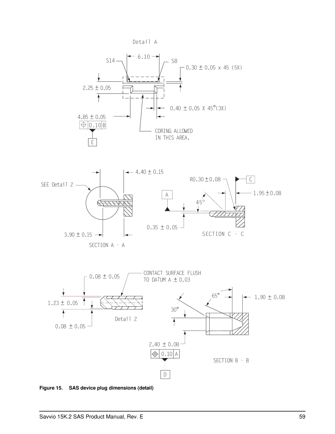
Image 70
Contents Standard Models Self-Encrypting Drive Models ST9146852SSST9146752SS ST973452SSST973352SSST9146652SS ST973252SS SED Fips 140-2 ModelsPage Contents About Fips About self-encrypting drives Defect and error managementInstallation Interface requirementsPage Savvio 15K.2 SAS Product Manual, Rev. E List of Figures Page Seagate Technology support services Seagate Online Support and ServicesScope Electromagnetic compatibility Applicable standards and reference documentationStandards Electromagnetic susceptibilityAustralian C-Tick Electromagnetic complianceElectromagnetic compliance for the European Union Korean MICReference documents European Union Restriction of Hazardous Substances RoHSGeneral description Standard features Media descriptionReliability PerformanceFormatted capacities Programmable drive capacity OptionsSeek performance characteristics Performance characteristicsInternal drive characteristics Access timeGeneral performance characteristics Format command execution timeStart/stop time Prefetch/multi-segmented cache control Cache operationCaching write data Prefetch operationRecoverable Errors Reliability specificationsError rates Unrecoverable ErrorsInterface errors Reliability and serviceSeek errors Preventive maintenancePerformance impact 4 S.M.A.R.TControlling S.M.A.R.T Reporting controlPredictive failures Temperature Log Page 0Dh Parameter Code DescriptionThermal monitor DST failure definition State of the drive prior to testingDrive Self Test DST ImplementationExtended test Function Code 010b Short and extended testsShort test Function Code 001b Log page entriesShipping Product warrantyProduct repair and return information AC power requirements Physical/electrical specificationsDC power requirements 146GB models DC power requirements Gbit mode Amps73GB models DC power requirements Power sequencing General DC power requirement notesConducted noise immunity Current profiles Current profile for 146GB modelsCurrent profile for 73GB models 146GB models in 6.0 Gbit operation Power dissipation146GB models in 3.0 Gbit operation 73GB models in 6.0 Gbit operation 73GB models in 3.0 Gbit operationEnvironmental limits Temperature a. OperatingRelative humidity Shock and vibration Effective altitude sea level a. OperatingShock Recommended mounting Vibration a. Operating-normal Air cleanlinessCorrosive environment Acoustics Mechanical specifications DimensionsPurpose About FipsLevel 2 security About self-encrypting drives Controlled accessAdmin SP Data encryptionDrive locking Default passwordRandom number generator RNG Data bandsSupported commands Authenticated firmware downloadPower requirements Cryptographic eraseDrive internal defects/errors Defect and error managementDrive error recovery procedures SAS system errors Media Pre-Scan Background Media ScanDeferred Auto-Reallocation Idle Read After Write Installation Drive orientationCooling Air flowDrive mounting GroundingSAS features Interface requirementsDual port support Scsi commands supported Supported commandsSupported commands Supported commands Supported commands Inquiry data Mode Sense dataSavvio inquiry data Page Mode Data Header 00 00 05 12 8B 00 10 Miscellaneous features Miscellaneous operating features and conditionsMiscellaneous status SAS physical interface Datum B Section C C Section a a Electrical description Physical characteristicsConnector requirements Pin descriptionsSAS pin descriptions SAS transmitters and receiversSignal characteristics General interface characteristics SAS-2 Specification complianceAdditional information Savvio 15K.2 SAS Product Manual, Rev. E Index NumericsIraw Msid Mtbf See also cooling