Dell M630 owner manual System board connectors, CPU1

Page 105

System board connectors

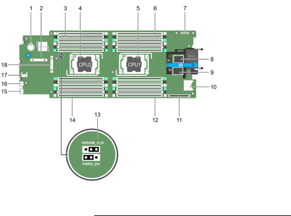
Figure 38. System board connectors

Table 6. System board connectors

Item

Connector

Description


1

BATTERY

Connector for the 3.0 V coin cell battery

2

STORAGE

Storage controller card connector

3

B3, B7, B11, B4, B8, B12

Memory module sockets (processor 2)

4

CPU2

Processor socket 2

5

CPU1

Processor socket 1

6

A1, A5, A9, A2, A6, A10

Memory module sockets (processor 1)

7

IDSDM/rSPI

IDSDM/rSPI card connector

8

MEZZ1_FAB_C

mezzanine card connector for the expansion bus

9

MEZZ2_FAB_B

mezzanine card connector for the expansion bus

10

VFLASH

SD vFlash card connector

11

bNDC

Network daughter card connector

12

A3, A7, A11, A4, A8, A12

Memory module sockets (processor 1)

105

Image 105
Contents Dell PowerEdge M630 Page Contents Installing and removing blade components Troubleshooting your system Using System Diagnostics 102 Jumpers and connectors 104Technical specifications 107 Getting help 112 About your system Front-panel features and indicatorsHard-drive/SSD indicator patterns Using USB diskette or USB DVD/CD drivesHard-drive/SSD indicators IDRAC Direct LED indicator codesIDRAC Direct LED indicator Documentation matrix Quick Resource Locator Setting up and configuring the iDRAC IP address Setting up your systemLogging in to iDRAC Installing the operating system Page Navigation keys About System SetupEntering System Setup System Setup Main MenuSystem Bios screen System Memory screen System Information screenATS Processor Settings screenSata Settings screen Post Page Network Settings screen Boot Settings screenIntegrated Devices screen 4GB Serial Communication screenC1E System Profile Settings screenSystem Security Settings screen Secure Boot Custom Policy Settings screen Miscellaneous Settings screen About Dell Lifecycle Controller Changing the boot order About Boot ManagerEntering Boot Manager Boot Manager main menuAssigning a system and/or setup password Choosing the system boot modeUsing your system password to secure your system Operating with a setup password enabled IDRAC Settings utilityEmbedded systems management Entering the iDRAC Settings utility Recommended tools Safety instructionsBefore working inside your system After working inside your systemRemoving the blade Removing and installing a bladeBlade cover O connector cover Removing or installing the blade Installing a bladeRemoving the system cover Removing and installing the system coverInstalling the system cover Inside the blade Inside the bladeRemoving the cooling shroud Cooling shroudInstalling the cooling shroud Processor/DIMM blankRemoving a processor/DIMM blank Removing and installing a processor/DIMM blank Installing a processor/DIMM blankLrdimm System memoryProcessor General memory module installation guidelines Advanced ECC Lockstep Mode-specific guidelinesSample memory configurations Memory configurations two processors Removing memory modules Removing the memory module Installing memory modulesModule mezzanine cards Mezzanine card installation guidelinesRemoving the mezzanine card Removing and installing the mezzanine cardIdsdm card optional Installing the mezzanine cardReplacing an SD card Replacing an SD card Internal USB keyReplacing the internal USB key Removing the Idsdm card Removing and installing the Idsdm cardInstalling the Idsdm card Removing the rSPI card RSPI card optionalInstalling the rSPI card SD vFlash cardReplacing the SD vFlash card Removing the Network Daughter Card Network Daughter CardNDC Processors Installing the Network Daughter CardRemoving a processor Installing and removing a heat sink Processor shield opening and closing lever sequence Installing and removing a processor Installing a processorPage Applying thermal grease on the top of the processor Hard drive/SSD installation guidelines Hard drives/SSDsHard-drive/SSD bay numbering Removing a hard drive/SSD Removing and installing a hard drive/SSDRemoving a hard-drive/SSD blank Installing a hard drive/SSDHard-drive/SSD blank Release latch Installing a hard-drive/SSD blank Hard drive/SSD Removing a 1.8 inch SSD from a 1.8 inch SSD carrier Removing the hard-drive/SSD cage Installing a 1.8 inch SSD in a 1.8 inch SSD carrierHard-drive/SSD cage Screw Guide pin Installing the hard-drive/SSD cage Hard-drive/SSD backplaneRemoving the hard-drive/SSD backplane Page Removing and installing the 1.8 inch x4 SSD backplane Installing the hard-drive/SSD backplane System boardRemoving the system board Page Hex nut screw System board Screw Installing the system board Restoring the Service Tag using Easy Restore Trusted Platform Module Entering the system Service Tag using System SetupRe-enabling the TPM for BitLocker users Replacing the Nvram backup battery Nvram backup batteryReplacing the Nvram backup battery Removing the PCIe extender/storage controller card Storage controller card/PCIe extender cardPage Installing the PCIe extender/storage controller card Troubleshooting your system Troubleshooting hard drives Troubleshooting USB devices Troubleshooting Solid State DrivesTroubleshooting processors Troubleshooting an internal SD cardTroubleshooting the Nvram backup battery Troubleshooting the blade system boardDiagnostic messages System messagesAlert messages Dell Embedded System Diagnostics When to use the Embedded System DiagnosticsRunning the Embedded System Diagnostics System diagnostic controls Running embedded system diagnostics from an external mediaSystem board jumper settings Jumpers and connectorsCPU1 System board connectorsDisabling a forgotten password Technical specifications USB Per ISO 14644-1 with a 95% upper confidence 110 Enclosure can be installed with blade Locating your system Service Tag Contacting DellDocumentation feedback 113