Texas Memory Systems RamSam-210 user manual Turning on the System, System Initialization

Page 14

2.7Turning on the System

The RamSan-210 will automatically power on when power is connected to the system. The only time the system will not automatically power on is when a user has initiated a Manual Shutdown of the system. In the event this has happened, it is necessary to press the top button on either power supply. Please see 2.6 Connecting the Power Supplies.

2.8System Initialization

The front panel display shows the current state of the boot process. Once the power is connected, the system will turn on automatically and the front panel will begin the power on sequence. The following will happen automatically (this boot sequence can also be monitored externally through the serial port or Ethernet port):

1.After approximately seven seconds, the RamSan-210 will power-up.

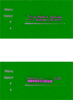
2.You should see “Texas Memory Systems” appear on the front panel, as well as RamSan-210”. Soon after that you will see “Booting” and “Initializing RamSan”.

3.After the firmware has finished booting, the front panel display will indicate

Bringing Disks Online”. The system disks take approximately 10 seconds each to spin-up.

4.The front panel will indicate

Restoring” and show a progress bar and give an estimated time till completion. Administrators may use this to determine how much time before the system is on-line. This information is also available through the telnet remote monitoring software in the status command. This process will take

approximately 2 minutes 15 seconds for every 4 gigabytes of memory in the system.

5.Once the system has restored data, the system will display “Status Good” and show the performance bars for each Fibre Channel port.

The system is now ready for normal operation.

Please see Chapter 7 – Troubleshooting for possible error conditions during start-up.

Please see Chapter 3 – Using the Front Panel for more information on configuring the Ethernet and monitoring system health.

- 9 -

Image 14
Contents Texas Memory SYSTEMS, INC Page Table of Contents Reset Status Figures Conventions PrefaceDocument Overview System Components IntroductionOverview Power Requirements Non-VolatilityPage Electro-Static Discharge Warning InstallationBattery Warning System InspectionRamSan-210 Layout Rack Mounting Connecting the Fibre Channel PortsConnecting the Power Supplies On switch Low Voltage Battery Turning on the System System InitializationUsing the Front Panel RamSan-210 Front PanelEthernet Setup Menu System LayoutManual Shutdown System Monitoring Page Connecting using telnet Connecting to the MCPConnecting using a terminal program Management Control Port MCPHelp MCP CommandsExit Page Lunconfig ManageReboot ResetStatus Hot Swapping Power Supplies Hot Swap ComponentsHot Swapping Disk Drives Hot Swapping FansPage Batteries Troubleshooting Warranty SpecificationsPhysical Characteristics Operating EnvironmentAppendix a RamSan-210 Replacement Parts Figure B-1 MCP31 Management Control ProcessorFigure B-3 PWR21 Power Supply Module Figure B-6 TDD21 18 gigabyte replacement hard drive