Lathem PC400TX manual RS-485 Connections, To make an RS485 connection

Page 14

8 - PC400 Terminal Installation & User’s Guide

RS-485 Connections

An RS-485 connection can attach up to 31 clocks to the computer, using a SWIFT-485+ converter that you can purchase from Lathem. You can wire the clocks directly to the converter (star configuration) or wire them to RS485 Terminal Screws; this allows you to run in a single line starting from the converter (multi-drop configuration).

With an RS-485 connection, you can use up to 4000 feet of cable to connect your clocks to the computer. Lathem recommends using CAT 5-UTP (unshielded twisted pair) data transmission cable.

To make an RS485 connection

Connect a SWIFT-485+ converter to an open COM port on your computer. If your COM port has 25 pins, you will need a 9-to-25 pin adapter that you can buy from a computer store.

Run the CAT 5 cable from the Swift-485+ to the first clock in the series . See Appendix A for the RS485 Network diagram
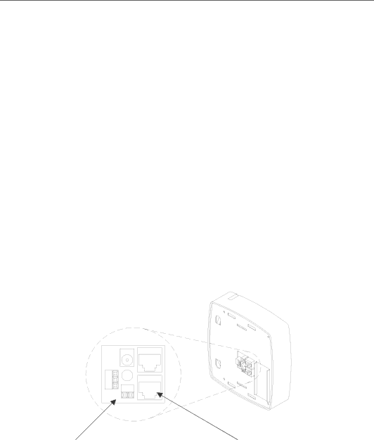
Unplug the RS485 screw terminal connector and attach a matched pair from your cable as shown in the diagram, plug in the connector. Make sure that the polarity is maintained. If your cable is terminated with a RJ-45 plug connect to the Terminal’s RS232 / RS485 communications port as shown in the diagram below, Figure 4.

(-)(+)

RS485 Screw

RS232/RS485

Terminal Connector

Port


Figure 4

Image 14
Contents Installation & User’s Guide PC400 & PC400TX TerminalFor Units Equipped with AN Internal Modem Support Agreements Support InformationGetting Help N T E N T S Page Page Features and Specifications WelcomePower Surges and Spikes Main Application Files TERMMGR.EXEWall Mount To install the back box Mount the ClockPage Desktop Mount To install the back box To make an RS232 connection Connect the Communication CablesRS-232 Connections RS-485 Connections To make an RS485 connectionModem Connections optional To make a Modem connectionPC400TX TCP/IP Connections optional To make a TCP/IP connectionMaximum of 4 Bells / Horns To connect your signaling devices power sourceBell Relay Connections To power up the clock Setup the ClockStarting the Terminal Setup Mode To start the Terminal Setup Mode Select 0 PM / 1 AMPIN Entry SetupMode Using the Clock To punch using a badgeTo transfer Supervisor Mode Schedule OverrideManual Bell Ring Wiring Diagrams RS-232 to HostRS-485 Network Multi Drop Network using the SWIFT485+ PC400 Terminal Block Diagram Installing a Modem Module in the PC400 ¾ Remove the PayClock 400 Terminal from the Back BoxPage Installing a TCP/IP 10Base T Module in the PC400 ¾ Install the 10Base T ModulePC400 Terminal Installation & User’s Guide Replacing an Existing PayClock 2000 or PC100 PC400 Terminal Installation & User’s Guide Troubleshoot the Clock Ground screw and ground wire attached to back box Limited One-Year Limited Warranty Index