Lathem PC400TX manual Supervisor Mode, Schedule Override

Page 23

PC400 Terminal Installation & User’s Guide - 17

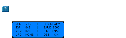
To see the Terminal Status

Press Terminal Status

The status screen displays

Supervisor Mode

Two supervisor modes are available for your PC400/PC400TX. You can override a lockout schedule and manually close the bell relay.

Schedule Override

With a supervisor badge, you can temporarily disable any lockout schedules set for the terminal, allowing the terminal to read the next badge that is entered. This provides supervisors a way to override a lockout schedule in special situations.

Before starting, be sure that the PC400/PC400TX is in normal operation mode with the time of day and date showing on the display. Otherwise, press * [exit] to resume normal operation.

To override a lockout zone for an employee In/Out punch:

1.With the time and date showing press # [enter], swipe your supervisor badge

2.“Supervisor Mode” with show on the terminal display

3.Within 5 seconds have the employee swipe their badge or PIN their badge number and press [#] enter

To override a lockout zone for an employee department transfer:

1.With the time and date showing press # [enter], swipe your supervisor badge

2.“Supervisor Mode” with show on the terminal display

3.Press the department transfer button 3 times

4.Within 5 seconds have the employee swipe their badge or PIN their badge number and press [#] enter

5.Key in the department number for the transfer

6.Press # [enter]

7.Press # [enter]

Note: Amount entries are allowed during a lockout schedule.

Image 23
Contents PC400 & PC400TX Terminal Installation & User’s GuideFor Units Equipped with AN Internal Modem Support Agreements Support InformationGetting Help N T E N T S Page Page Welcome Features and SpecificationsPower Surges and Spikes TERMMGR.EXE Main Application FilesMount the Clock Wall Mount To install the back boxPage Desktop Mount To install the back box To make an RS232 connection Connect the Communication CablesRS-232 Connections To make an RS485 connection RS-485 ConnectionsTo make a Modem connection Modem Connections optionalTo make a TCP/IP connection PC400TX TCP/IP Connections optionalMaximum of 4 Bells / Horns To connect your signaling devices power sourceBell Relay Connections To power up the clock Setup the ClockStarting the Terminal Setup Mode Select 0 PM / 1 AM To start the Terminal Setup ModePIN Entry SetupMode To punch using a badge Using the ClockTo transfer Schedule Override Supervisor ModeManual Bell Ring RS-232 to Host Wiring DiagramsRS-485 Network Multi Drop Network using the SWIFT485+ PC400 Terminal Block Diagram ¾ Remove the PayClock 400 Terminal from the Back Box Installing a Modem Module in the PC400Page ¾ Install the 10Base T Module Installing a TCP/IP 10Base T Module in the PC400PC400 Terminal Installation & User’s Guide Replacing an Existing PayClock 2000 or PC100 PC400 Terminal Installation & User’s Guide Troubleshoot the Clock Ground screw and ground wire attached to back box Limited One-Year Limited Warranty Index