JVC AV-61S902 manual Cable and VCR Connections, Diagram #1 Cable box

Page 12

AV-61S902(E) 1/12/01 3:15 PM Page 12

Connections

Cable and VCR Connections

There are three basic antenna or cable connections:

If you plan to only connect an antenna or to a cable television system, please refer to Diagram #1.

If you plan to connect a VCR and have an antenna or a cable television system that does not require the use of a cable box, please refer to Diagram #2.
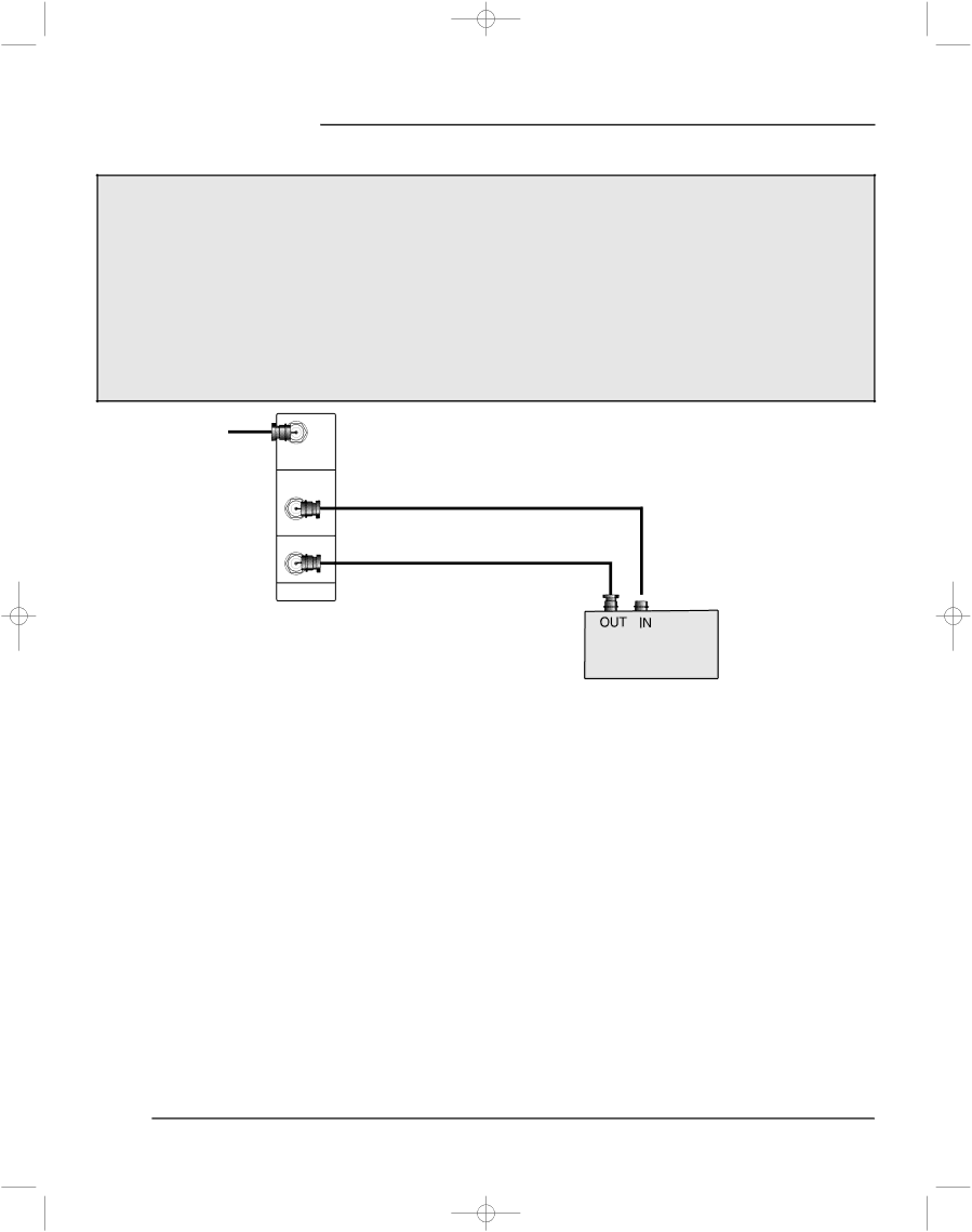
If you plan to connect a VCR and have a cable system that requires the use of a box to receive any or all cable channels, please refer to Diagram #3.

Please note: In the following diagrams, only the portion of the AV-61S902’s rear panel jacks that will be used for the connection described will be shown. For an illustration of the complete rear panel, please see page 11.

• For instructions on connecting a satellite or HDTV receiver, please see page 15.

INPUT

A

SPLIT

OUT

INPUT

B

75Ω

( VHF / UHF )

Diagram #1

Cable box

1)Connect a coaxial cable out from the cable TV wall outlet or external antenna into the RF Input A.

2)Connect a coaxial cable out from the Cable Split Out RF jack into the RF input on the cable box.

3)Connect a coaxial cable out from the Cable Box RF Output jack into the television’s RF Input B.

If you are connecting an external antenna or to a cable system that does not require the use of a cable box to receive any or all cable channels, follow step 1 only.

Coaxial cables are not included with the television.

12

Image 12
Contents Projection Television Users Guide Important Safety Precautions USE Clean the air filter once every three months WelcomeOrder to be able to use the television for a long time Do not block the ventilation holesTelevision requires a lot of electric power Do not turn the power on and off repeatedly in a short timeILA element characteristics Lamp is a consumable itemTable of Contents Troubleshooting Button FunctionsAppendices Check the accessories Check that nothing is missing Prepare the remote controlIntroduction Connect the antenna Adjusting the volume Cancelling the shutting off Watching television Choosing a channelConnections Checklist ConnectionsKnow your jacks and plugs most are color coded Front Panel Diagram Rear Panel DiagramDiagram #1 Cable box Cable and VCR ConnectionsVideo Connection Diagram #3 DTV Decoder Connection BlueRed DTV decoder DVD Player Connection AV Compu-Link Front Panel Inputs Home Theater Remote Control Install the BatteriesRemote Control Basics Cable Box or Satellite setup Remote ProgrammingVCR setup MGADVD setup JVCSearch Codes Cable/Satellite Search Codes FunctionVCR Search Codes Function DVD Player Search Codes FunctionOnscreen Menus Onscreen Menu SystemUsing the Onscreen Menus Plug In Menu Plug In MenuAuto Tuner Setup StartFinish Initial Setup Initial Setup MenuAntenna INPUT-A INPUT-B Channel Summary Channel Guard MessageChip ChipMpaa Motion Picture Assoc. of America Ratings Special Note about RatingsSet Ratings Guidelines To Set TV Ratings LevelsUnrated Programs Set Lock CodeInitial Setup LanguageFRE SPA Vertical Position DSD OFFDIGITAL-IN Size Picture Adjust Picture AdjustTint ColorPicture BrightDetail YNR DNR OFFNoise Muting OFF SET Video StatusSound Adjust Sound AdjustBass TrebleSome Sound Advice SAP MonoMID LOW TV Speaker OFFAudio Settings Sound ModeDolby Pro Logic Order to enjoy Dolby Surround sound Enjoy Dolby Surround soundPro Logic 3D-Phonic Other Sound ModesCLOCK/TIMERS Setting the ON/OFF TimerAspect AspectButton Functions SplitFreeze SwapSleep Timer Sleep Timer MessageMenu ExitSound MutingVideo Status Natural CinemaNumber Buttons 10 Key Pad 100+ ButtonReturn+ Input Menu on TV’s front panelLight TV/CATV Switch VCR/DVD SwitchVCR Buttons DVD ButtonsTroubleshooting Problems CheckTroubleshooting Cleaning the Filters Appendix aCleaning the filter Reinstall the filter coverReinstall the speaker covers Caring for the CabinetReplacement Lamp Kit Appendix BChanging the Lamp Replacing the LampRemove the left speaker panel Removing the filter unitInstall the new lamp unit Reinstall the speaker panelRemoving the lamp unit Filter not properly reinstalled Recycling InformationAppendix C LED DisplayStarting Up Shutting DownLimited Warranty Parts 1 Year Labor 1 Year LampAuthorized Service Centers Don’t service the television yourselfAccessories For service in Canada Toll Free 1 800Specifications ModelJVC Company of America JVC CANADA, INC