ASSEMBLY INSTRUCTIONS
RIGHT
4
Slide this side of the
CARRIAGE(42) into the
RIGHT RAIL(10)
2
Keep the gap 2 to 3 inches.
1
Screw the bolts half way
into the LEFT RAIL(9).
3
Slide this side of the
CARRIAGE(42) into the
LEFT RAIL(9)
5
Push this end of the LEFT RAIL(9)
to the FRONT FRAME(1) andLEFT secure with the bolts.
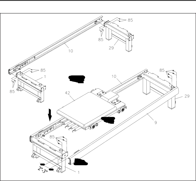
STEP 3: Attach the RIGHT RAIL(10) to the FRONT FRAME(1) and REAR FRAME(29) with BUTTON
HEAD BOLTS(M8x1.25x15mm)(85).
HINT: Study the illustration carefully to make sure that the FRONT FRAME(1) and REAR FRAME(29) are not reversed. The FRONT FRAME(1) has brackets for the WHEELS(8) near the bottom and small holes on the top surface. Make sure that the RAILS(9, 10) are not upside down. Make sure that the LEFT RAIL(9) and RIGHT RAIL(10) are not reversed.
STEP 4: Please use two people to assemble the AeroPilates![]() Pro XP686. Use the following procedure to assemble the LEFT RAIL(9) and CARRIAGE(42):
Pro XP686. Use the following procedure to assemble the LEFT RAIL(9) and CARRIAGE(42):
NOTE: Review sequence one through five in the illustration above before beginning this procedure.
a.Have your assistant hold the front end of the LEFT RAIL(9). Attach the back end of the LEFT RAIL(9) to the REAR FRAME(29) with BUTTON HEAD BOLTS(M8x1.25x15mm)(85). Screw the bolts half way into the LEFT RAIL(9).
b.Keep the gap between front end of the LEFT RAIL(9) and the FRONT FRAME(1) about two to three inches. Then lift up the CARRIAGE(42) and slide it into the rails as shown in the illustration.
c.Push the front end of the LEFT RAIL(9) to the FRONT FRAME(1) and secure with BUTTON HEAD BOLTS(M8x1.25x15mm)(85). Tighten all the bolts.
8