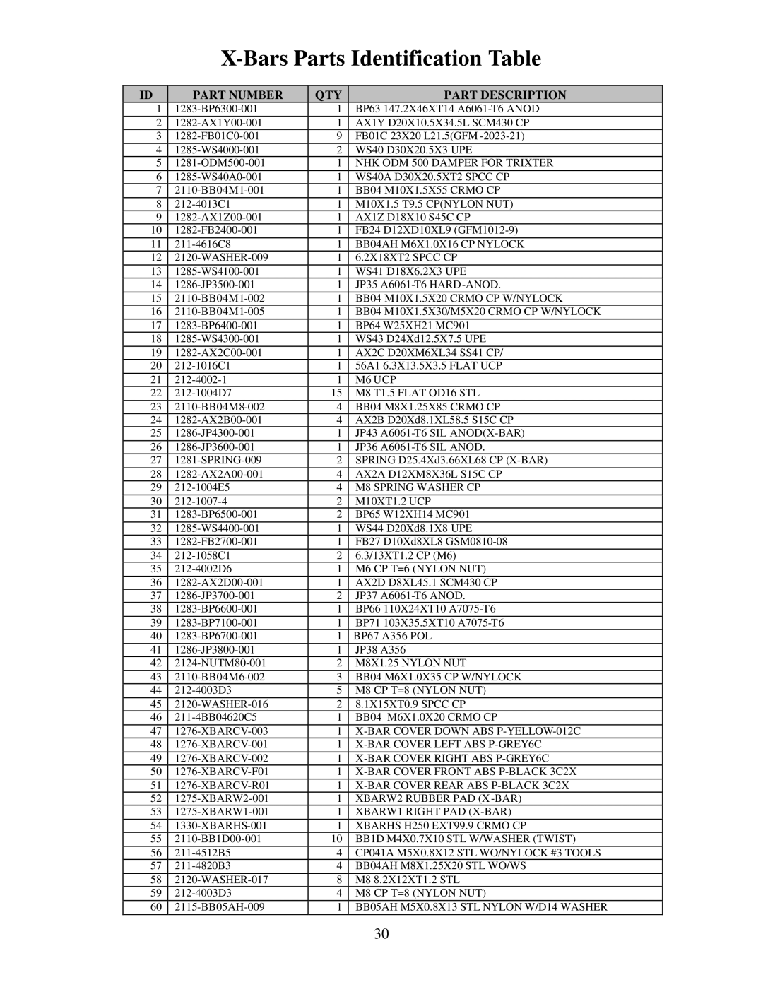
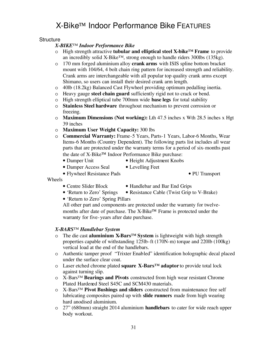
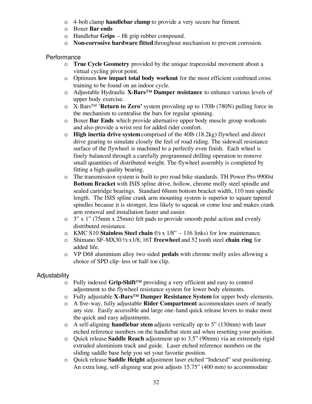
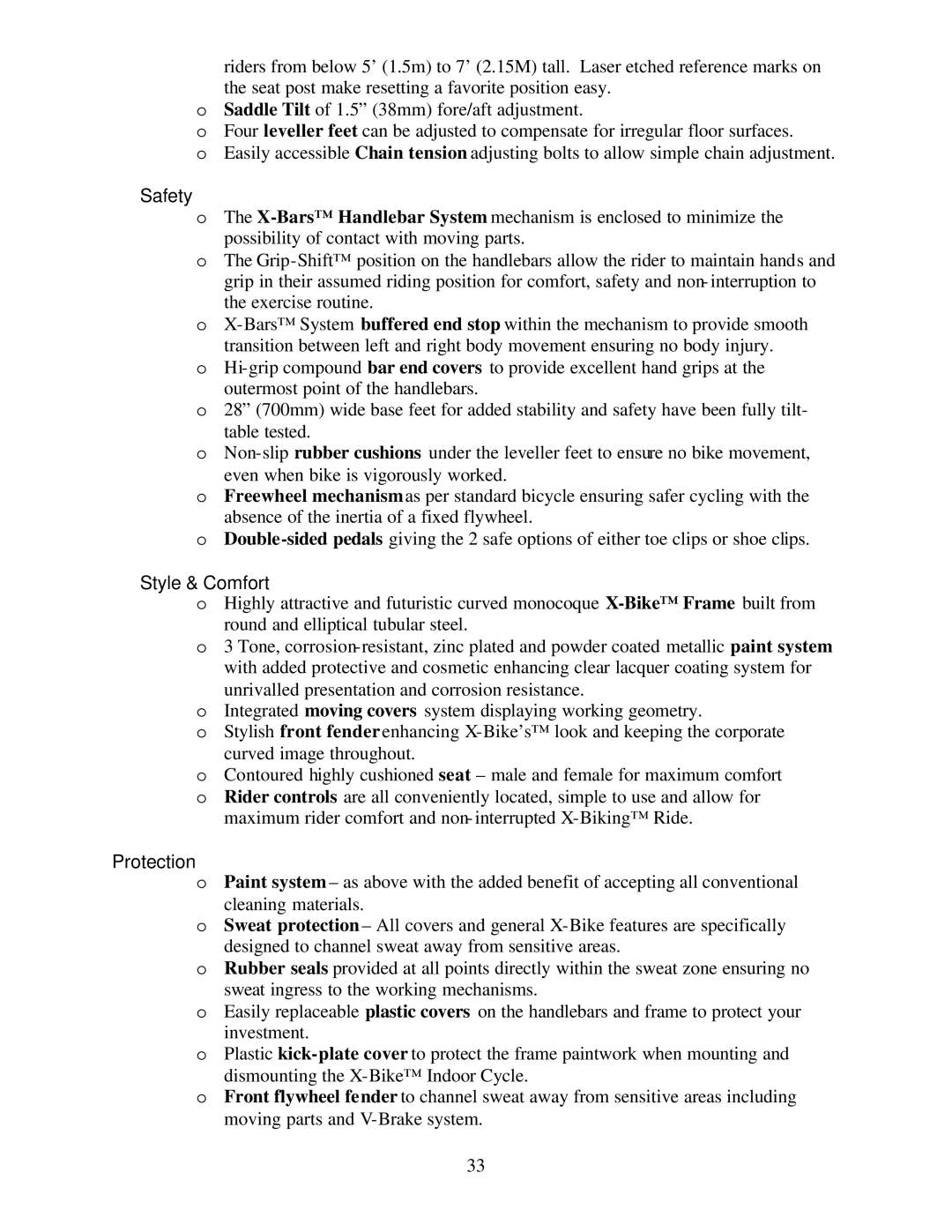
Trixter X-Bike manual Monthly, Chain Tensioning, Axle Position Markings Chain Adjusting Bolts

Page 16

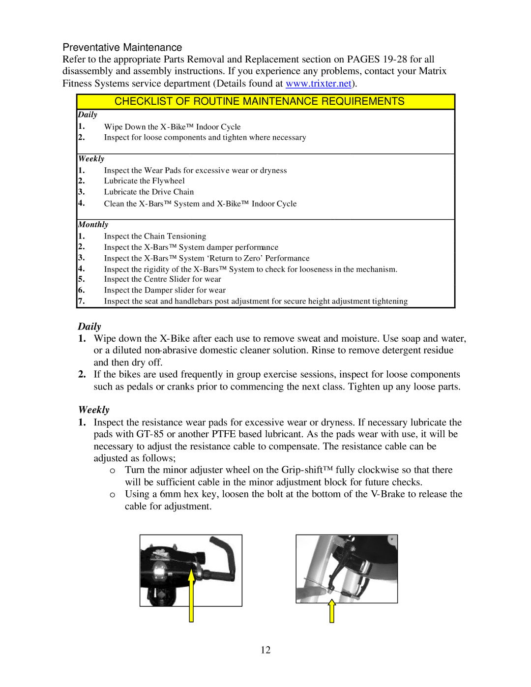
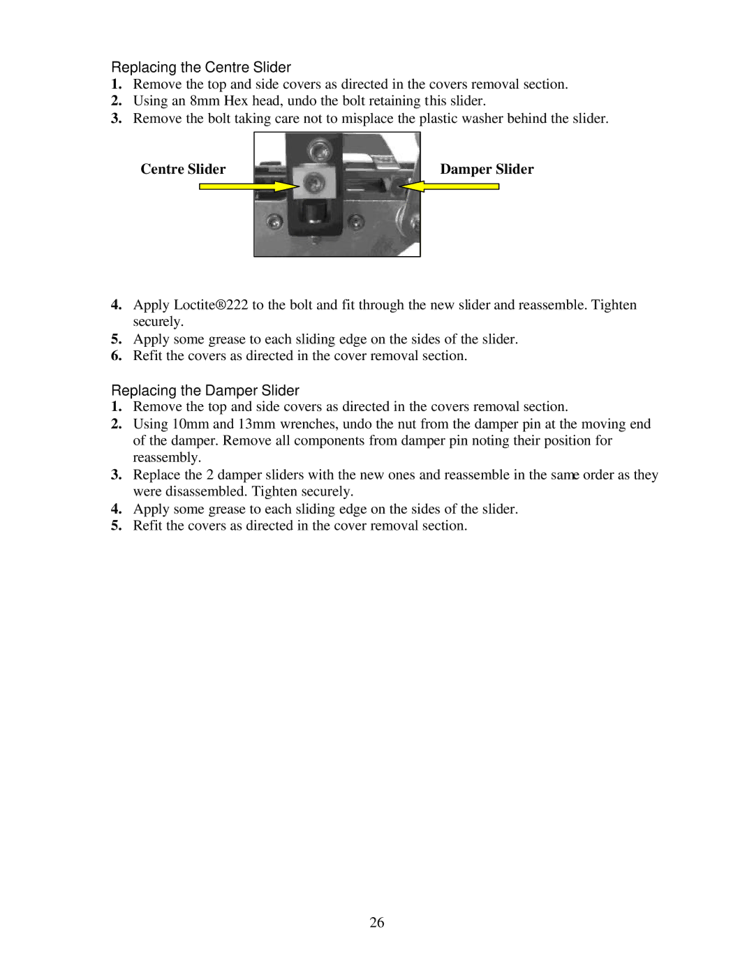
Minor Cable Adjuster

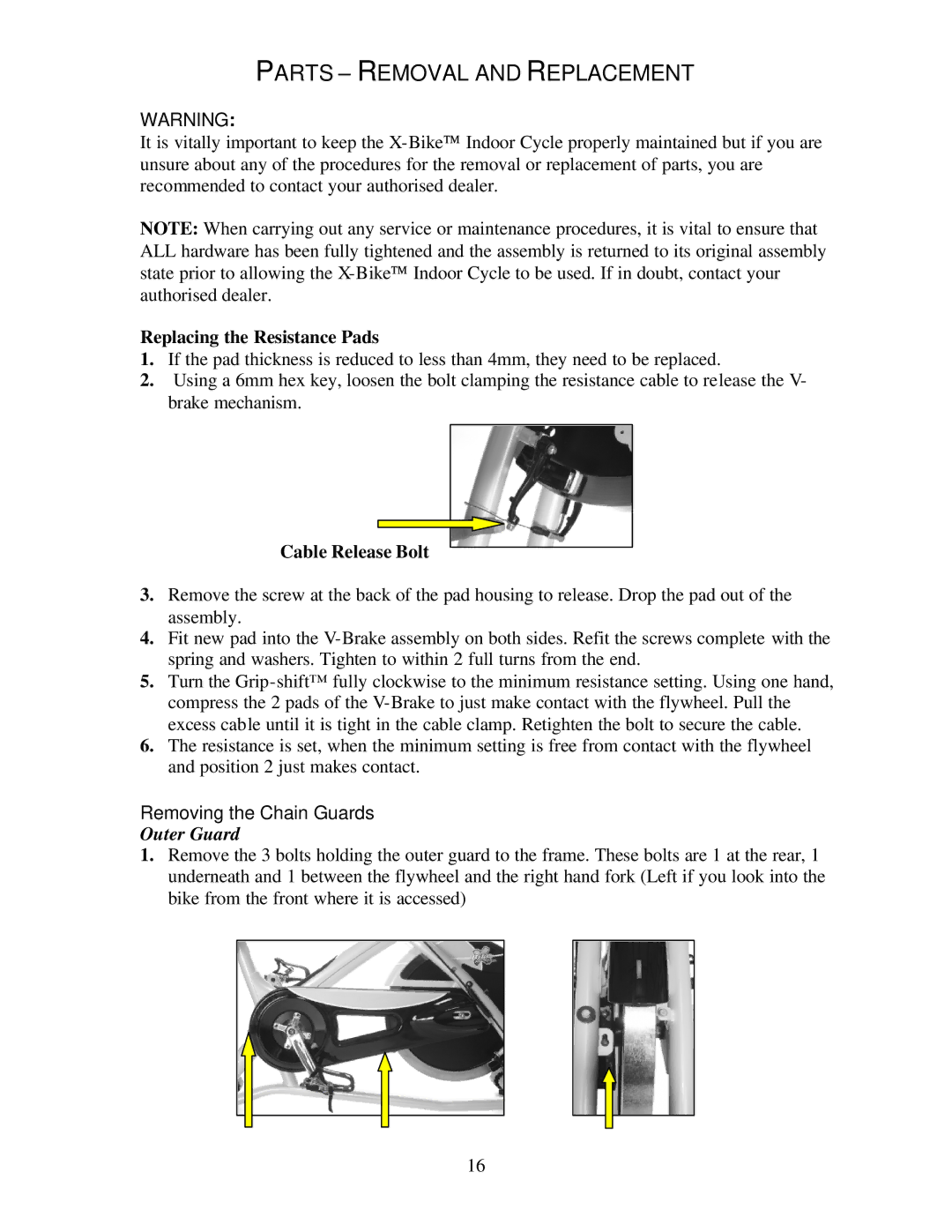
Cable Release Bolt

oTurn the Grip-shift™ fully clockwise to the minimum resistance setting. Using one hand, compress the 2 pads of the V-Brake to just make contact with the

flywheel. Pull the excess cable until it is tight in the cable clamp. Retighten the bolt to secure the cable.

oThe resistance is set, when position 1 or minimum setting is free from contact

with the flywheel and position 2 just makes contact. Use minor adjustment if required.

oIf the pad thickness is reduced to less than 4mm, they need to be changed. (See Pad Changing instructions in Parts – Removal and Replacement)

2.Wipe down the flywheel with WD-40® or equivalent light oil spray. This lubricant will clean the surface of the flywheel and help prevent rust.

3.Lubricating the chain – Using a spray can with an extension nozzle; you can gain access to the chain from the front of the chain guard with general light maintenance oil.

4.To keep the X-Bike looking new, wipe the general bodywork of the X-Bike and X-Bars with a clean damp cloth. Use conventional dish washing detergent but never use abrasive materials to clean the bike. Be certain to wipe off all traces of perspiration when you are finished as it contains salt and other corrosive substances that can damage surfaces and/or leave a white residue.

5.If you should need assistance or service, contact your service department (See details at www.trixter.net)

Monthly

1.Chain Tensioning

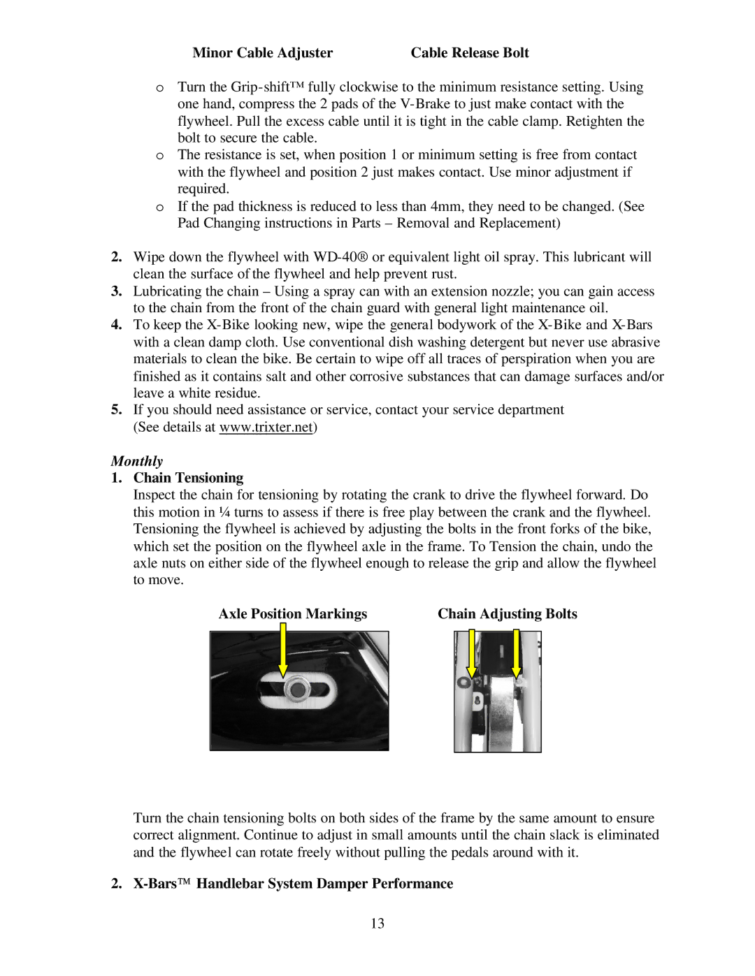
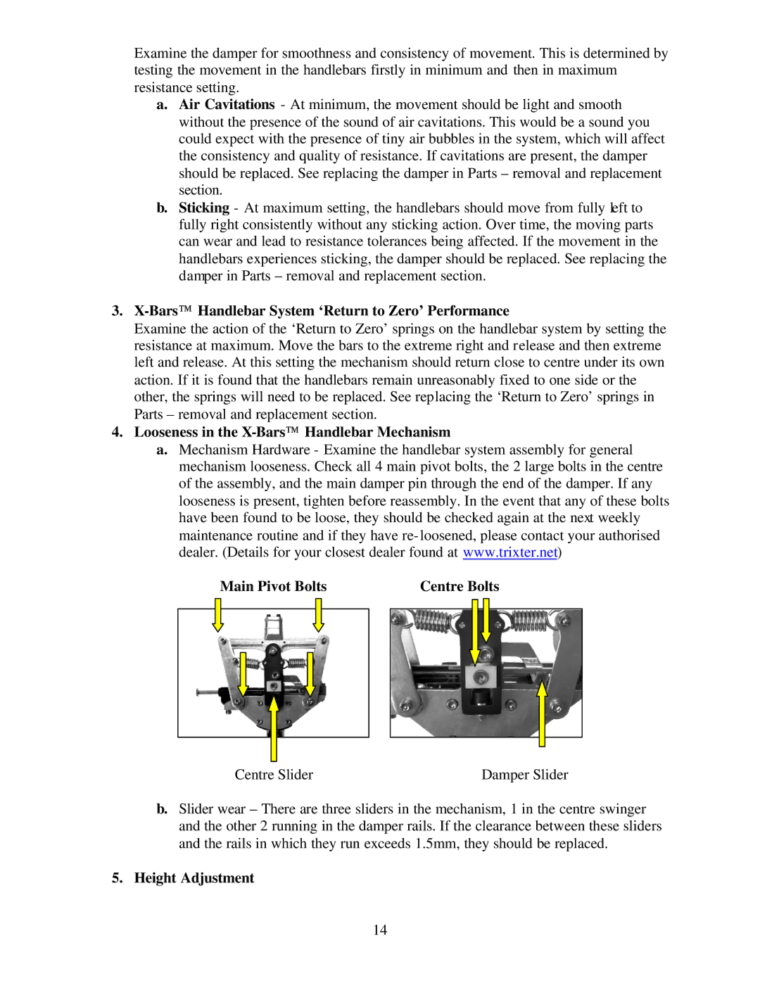
Inspect the chain for tensioning by rotating the crank to drive the flywheel forward. Do this motion in ¼ turns to assess if there is free play between the crank and the flywheel. Tensioning the flywheel is achieved by adjusting the bolts in the front forks of the bike, which set the position on the flywheel axle in the frame. To Tension the chain, undo the axle nuts on either side of the flywheel enough to release the grip and allow the flywheel to move.

Axle Position Markings

Chain Adjusting Bolts


Turn the chain tensioning bolts on both sides of the frame by the same amount to ensure correct alignment. Continue to adjust in small amounts until the chain slack is eliminated and the flywheel can rotate freely without pulling the pedals around with it.

2. X-BarsHandlebar System Damper Performance

13
Image 16
Contents Page Page Table of Contents Safety Information Page Dimensions of the X-Bike IntroductionBike Indoor Performance Bike Biking Indoor Cycling ProgramsSetting UP the X-BIKEIndoor Performance Cycle Installation & AdjustmentRemove the bike and components from the shipping carton Assembling the Bike Seat Fore/Aft Adjust Lever Seat Height Adjuster KnobLeveller Foot Handlebar and Bar Ends Height Adjuster Knob Seat Adjustment Adjusting the BikeAdjusting the Flywheel Resistance Handlebar Bar Height Adjustment Minor Cable AdjusterPedal Strap Adjustment Using Your X-BIKEINDOOR Performance Bike General Exercise GuidelinesPedalling Pumping the X-BarsMounting and Dismounting Your First WorkoutBasic Instructions Pedalling ResistanceMaintenance Instructions Helpful HintsFront of Bike Frame Serial Number Tool ListDaily Preventative MaintenanceWeekly Axle Position Markings Chain Adjusting Bolts MonthlyChain Tensioning BarsHandlebar System Damper PerformanceHeight Adjustment BarsHandlebar System ‘Return to Zero’ PerformancePage Parts Removal and Replacement Replacing the Resistance PadsCable Release Bolt Removing the Chain GuardsBolt Inner GuardRemoving the Flywheel Replacing the ChainReplacing the Handlebars Replacing the Grip-shiftLeft Crank Arm Removing Pedal Crank ArmsCrank Bolt Removal Crank Arm Puller Right Crank Arm Tightening the Bottom Bracket BearingsTop Cover Seat Clamp BoltFront Bolts Rear Bolts Side CoversSide Cover Bolts Bottom CoverPage Outer Spring Loop Inner Spring Loop Replacing the Return to Zero SpringsLubricating the Mechanism Page Centre Slider Damper Slider Replacing the Centre SliderReplacing the Damper Slider Bike Frame Specifications Equipment and Technical InformationExploded View & Parts Identification Bars Exploded View Bars Parts Identification Table Maximum User Weight Capacity 300 lbs StructureBike Indoor Performance Bike Bars Handlebar SystemAdjustability PerformanceStyle & Comfort SafetyProtection Service and Maintenance Easily accessible chain tensioning pointsAdditional Features & Options Mobility & StorageBike Indoor Performance Bike Warranty Card Thank YOU for Purchasing AN X-BIKEINDOOR Performance BikeLimited Warranty Limited RemedyWarranty Registration Card Thank YOU Index