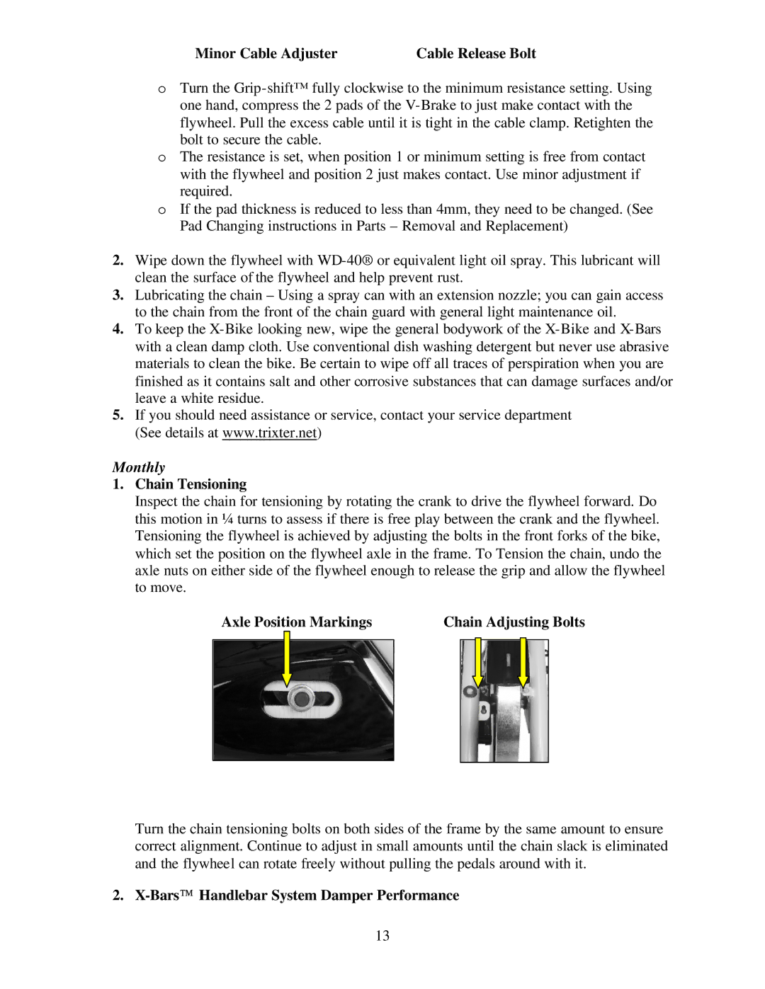
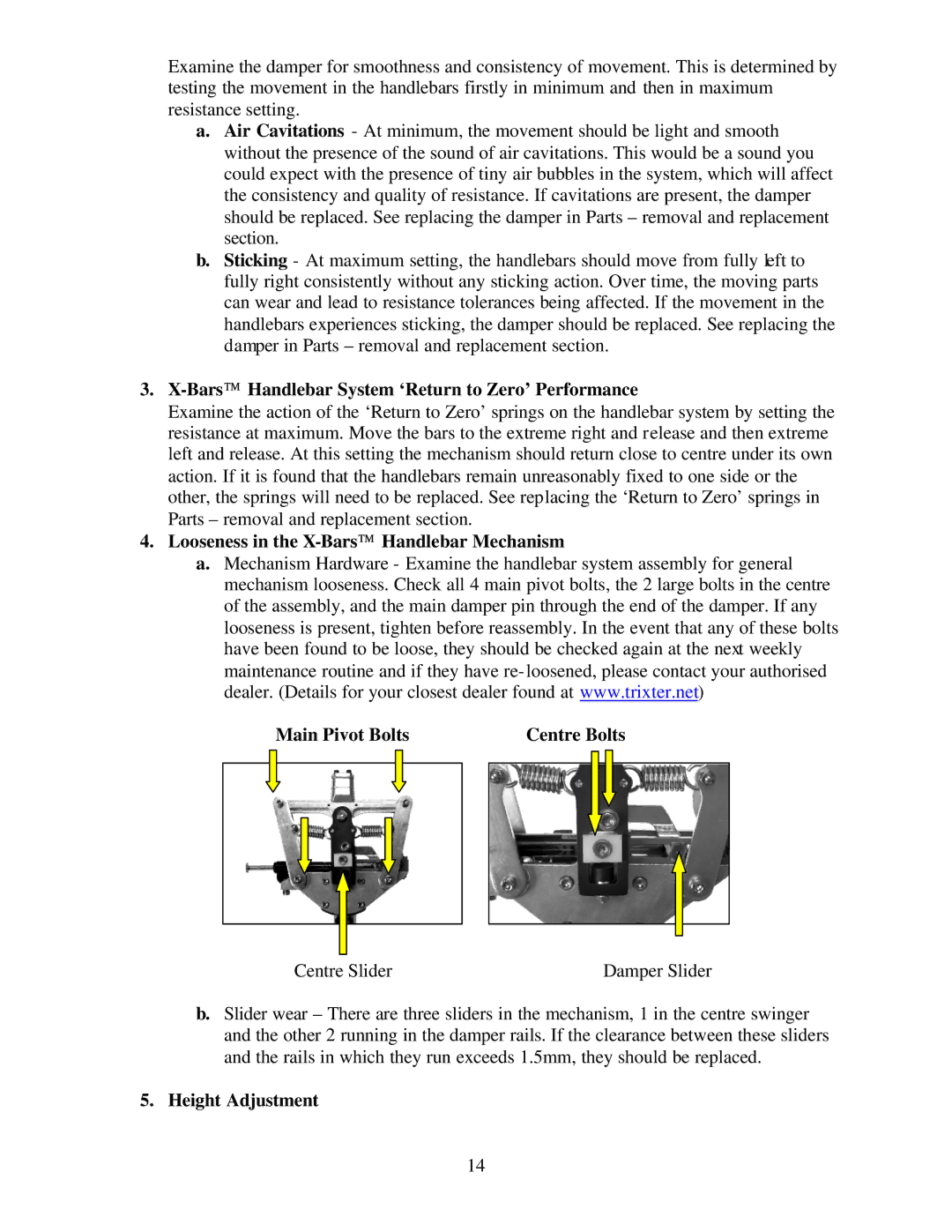
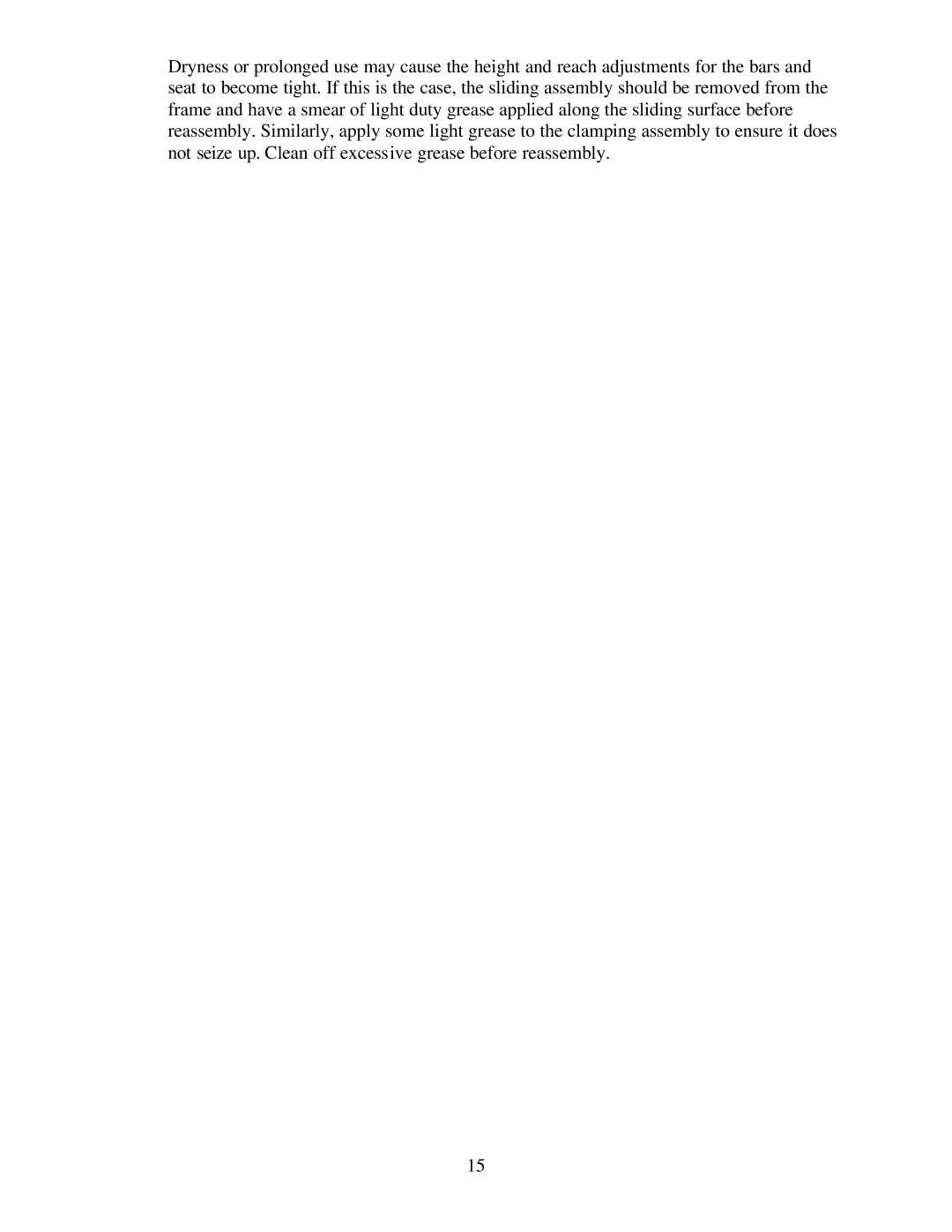
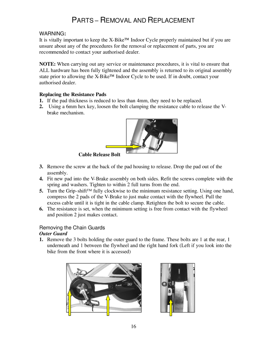
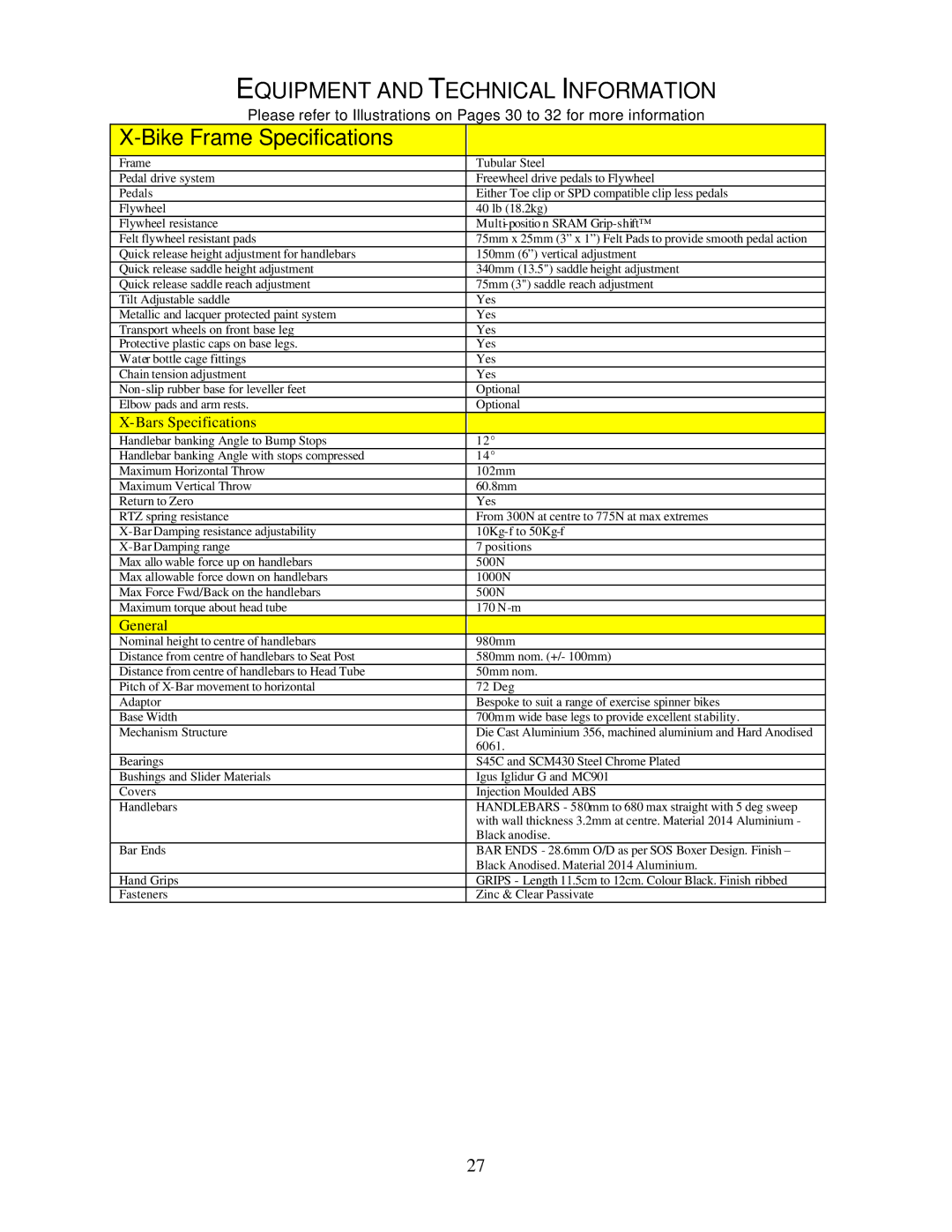
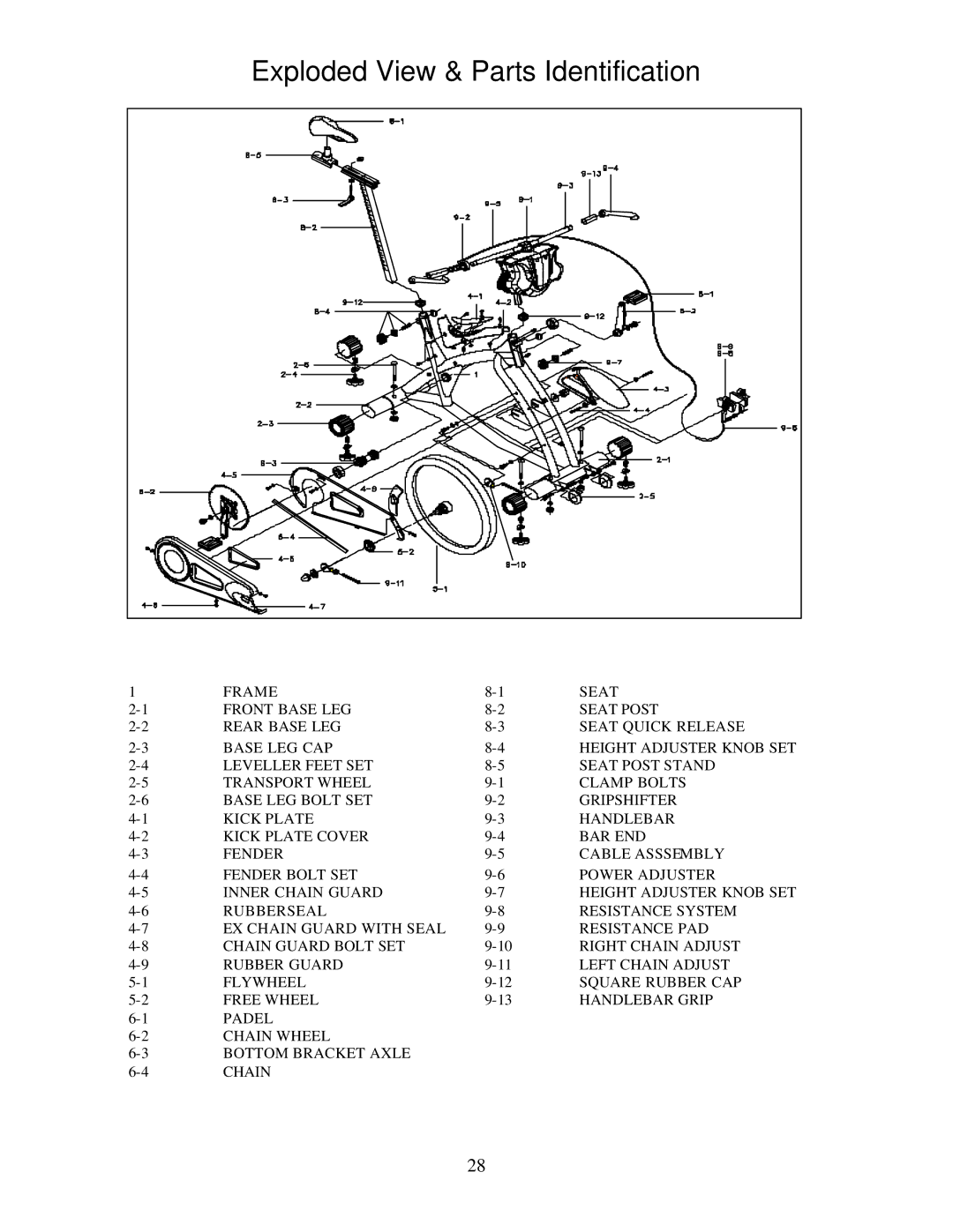
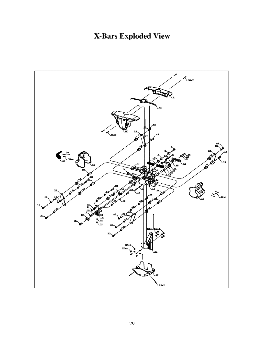
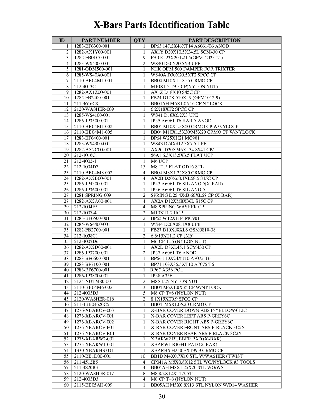
Trixter X-Bike manual Right Crank Arm, Tightening the Bottom Bracket Bearings

Page 23

Right Crank Arm

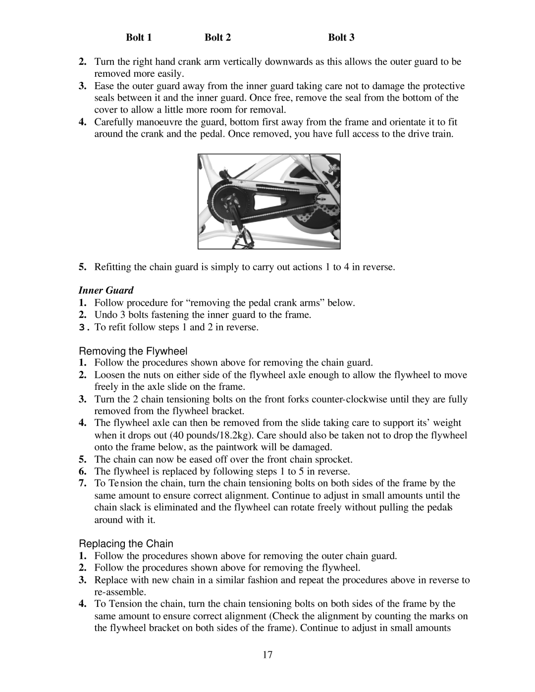
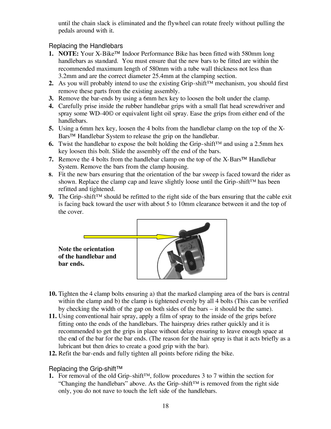
1.Follow procedures for “Removing the Chain Guard” above.

2.Use an 8mm Hex key to remove the pedal crank bolt.

3.Thread a bicycle crank arm puller onto the crank arm shaft.

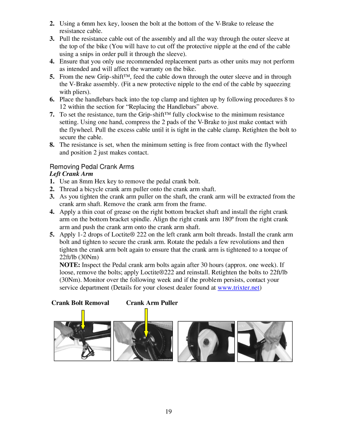
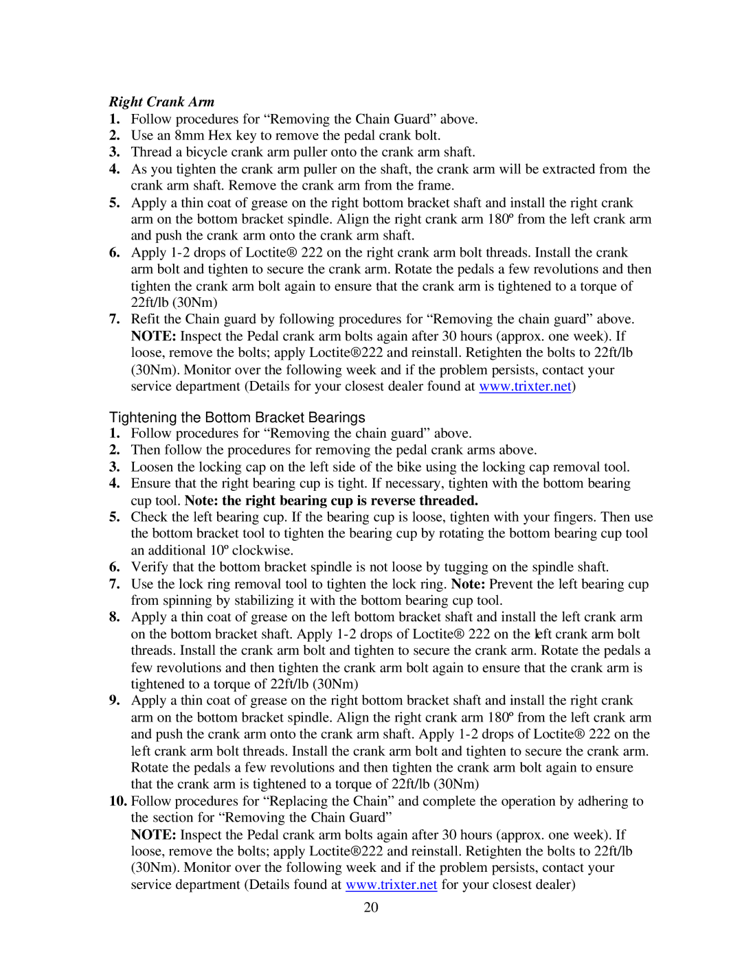
4.As you tighten the crank arm puller on the shaft, the crank arm will be extracted from the crank arm shaft. Remove the crank arm from the frame.

5.Apply a thin coat of grease on the right bottom bracket shaft and install the right crank arm on the bottom bracket spindle. Align the right crank arm 180º from the left crank arm and push the crank arm onto the crank arm shaft.

6.Apply 1-2 drops of Loctite® 222 on the right crank arm bolt threads. Install the crank arm bolt and tighten to secure the crank arm. Rotate the pedals a few revolutions and then tighten the crank arm bolt again to ensure that the crank arm is tightened to a torque of 22ft/lb (30Nm)

7.Refit the Chain guard by following procedures for “Removing the chain guard” above. NOTE: Inspect the Pedal crank arm bolts again after 30 hours (approx. one week). If loose, remove the bolts; apply Loctite®222 and reinstall. Retighten the bolts to 22ft/lb (30Nm). Monitor over the following week and if the problem persists, contact your service department (Details for your closest dealer found at www.trixter.net)

Tightening the Bottom Bracket Bearings

1.Follow procedures for “Removing the chain guard” above.

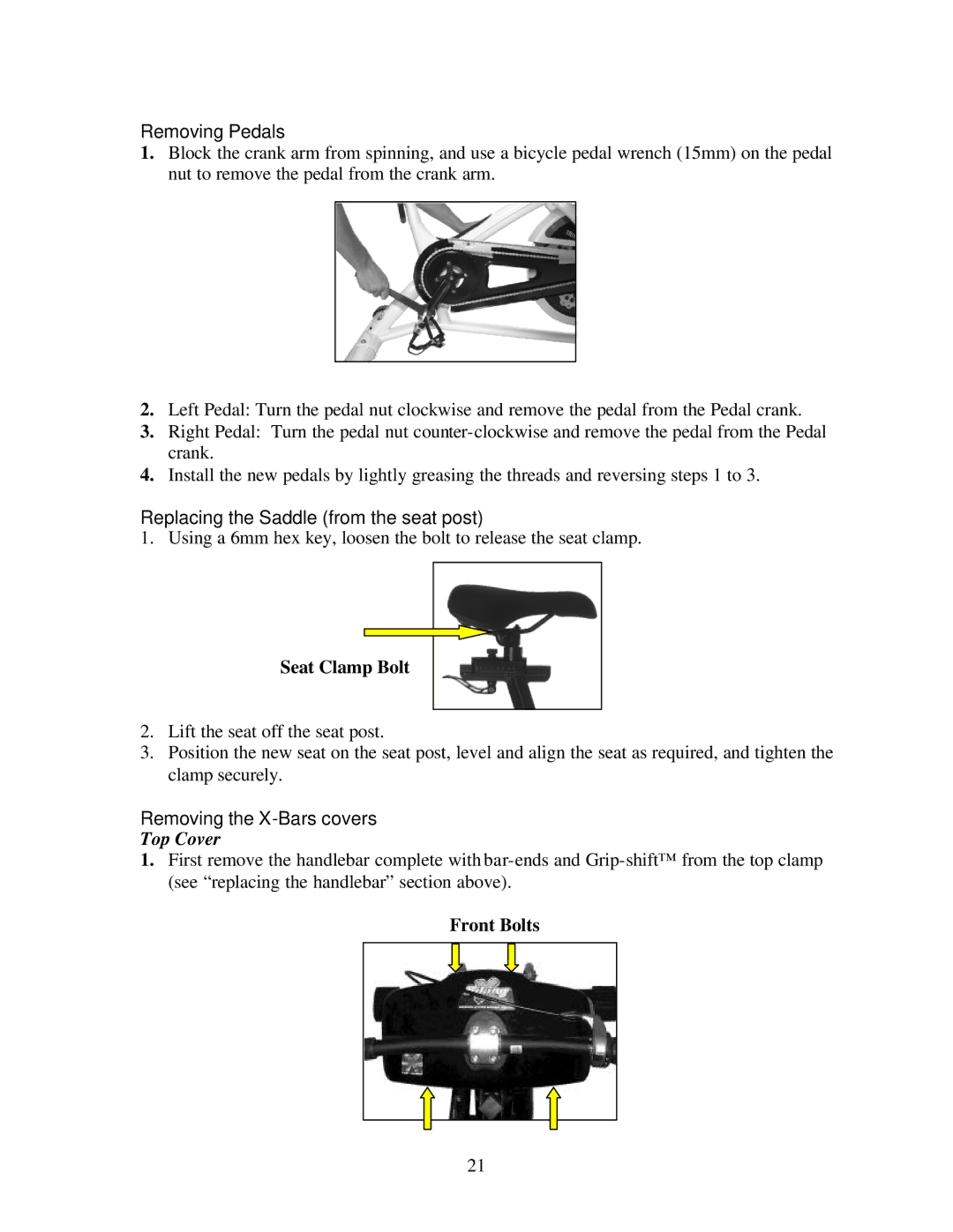
2.Then follow the procedures for removing the pedal crank arms above.

3.Loosen the locking cap on the left side of the bike using the locking cap removal tool.

4.Ensure that the right bearing cup is tight. If necessary, tighten with the bottom bearing cup tool. Note: the right bearing cup is reverse threaded.

5.Check the left bearing cup. If the bearing cup is loose, tighten with your fingers. Then use the bottom bracket tool to tighten the bearing cup by rotating the bottom bearing cup tool an additional 10º clockwise.

6.Verify that the bottom bracket spindle is not loose by tugging on the spindle shaft.

7.Use the lock ring removal tool to tighten the lock ring. Note: Prevent the left bearing cup from spinning by stabilizing it with the bottom bearing cup tool.

8.Apply a thin coat of grease on the left bottom bracket shaft and install the left crank arm on the bottom bracket shaft. Apply 1-2 drops of Loctite® 222 on the left crank arm bolt threads. Install the crank arm bolt and tighten to secure the crank arm. Rotate the pedals a few revolutions and then tighten the crank arm bolt again to ensure that the crank arm is tightened to a torque of 22ft/lb (30Nm)

9.Apply a thin coat of grease on the right bottom bracket shaft and install the right crank arm on the bottom bracket spindle. Align the right crank arm 180º from the left crank arm and push the crank arm onto the crank arm shaft. Apply 1-2 drops of Loctite® 222 on the left crank arm bolt threads. Install the crank arm bolt and tighten to secure the crank arm. Rotate the pedals a few revolutions and then tighten the crank arm bolt again to ensure that the crank arm is tightened to a torque of 22ft/lb (30Nm)

10.Follow procedures for “Replacing the Chain” and complete the operation by adhering to the section for “Removing the Chain Guard”

NOTE: Inspect the Pedal crank arm bolts again after 30 hours (approx. one week). If loose, remove the bolts; apply Loctite®222 and reinstall. Retighten the bolts to 22ft/lb (30Nm). Monitor over the following week and if the problem persists, contact your service department (Details found at www.trixter.net for your closest dealer)

20
Image 23
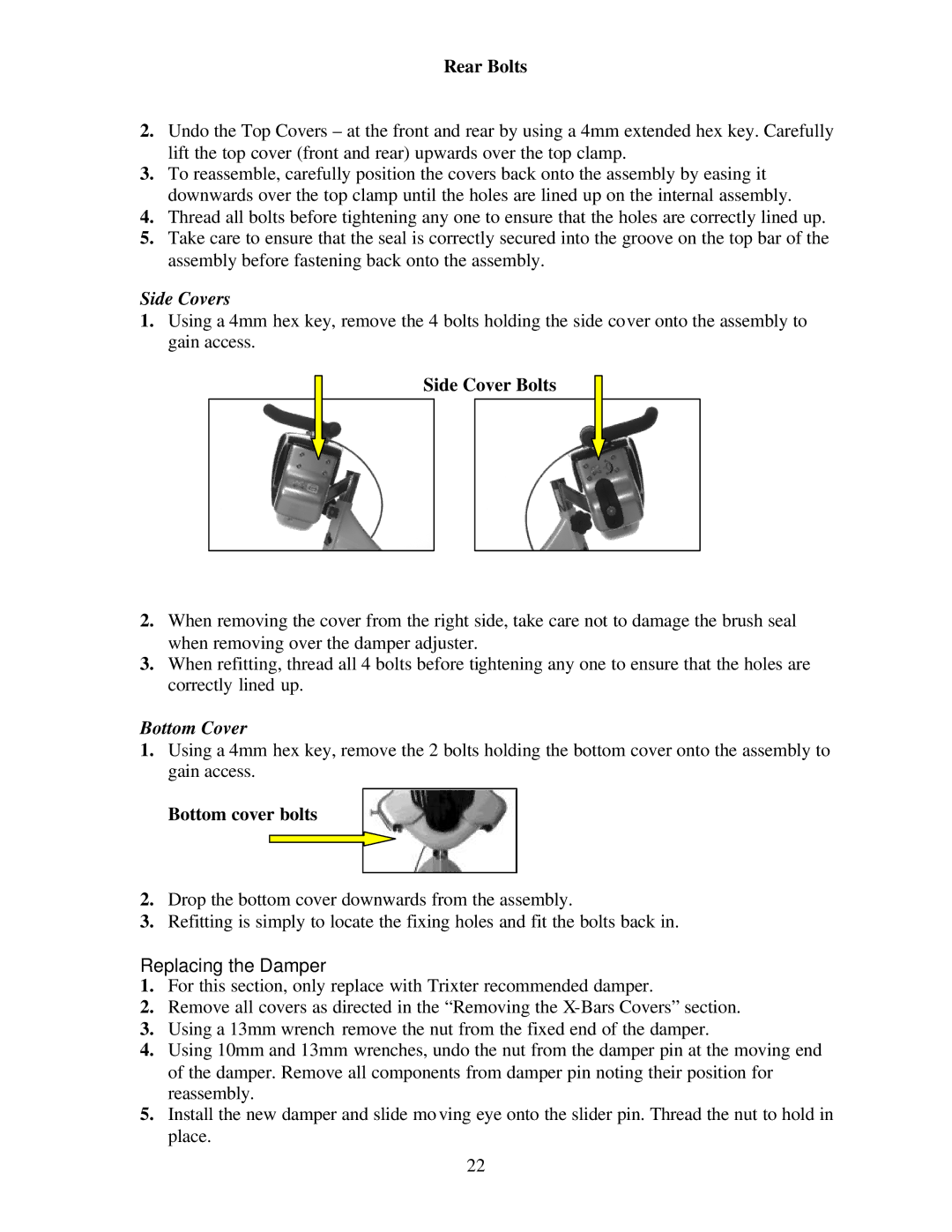
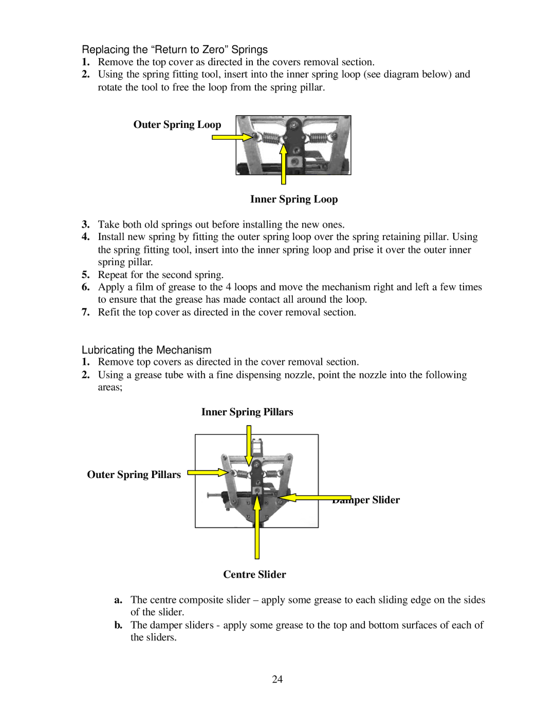
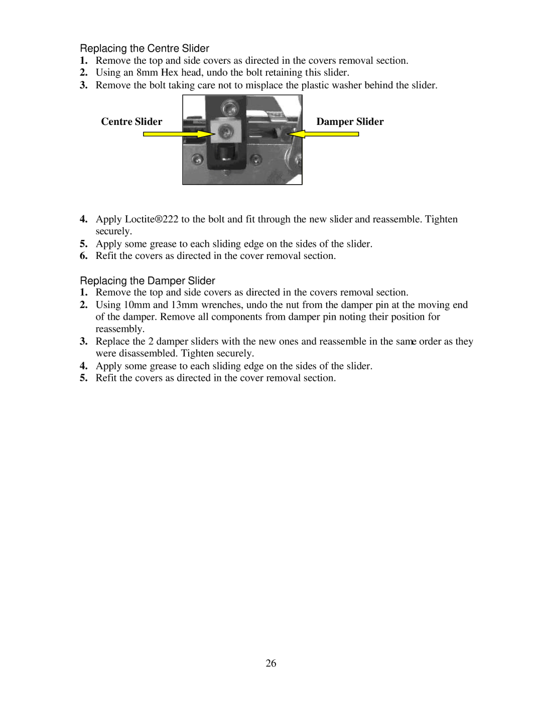
Contents Page Page Table of Contents Safety Information Page Biking Indoor Cycling Programs Dimensions of the X-BikeIntroduction Bike Indoor Performance BikeRemove the bike and components from the shipping carton Installation & AdjustmentSetting UP the X-BIKEIndoor Performance Cycle Leveller Foot Seat Fore/Aft Adjust Lever Seat Height Adjuster KnobAssembling the Bike Handlebar and Bar Ends Height Adjuster Knob Adjusting the Flywheel Resistance Adjusting the BikeSeat Adjustment Pedal Strap Adjustment Minor Cable AdjusterHandlebar Bar Height Adjustment Pumping the X-Bars Using Your X-BIKEINDOOR Performance BikeGeneral Exercise Guidelines PedallingPedalling Resistance Mounting and DismountingYour First Workout Basic InstructionsTool List Maintenance InstructionsHelpful Hints Front of Bike Frame Serial NumberWeekly Preventative MaintenanceDaily BarsHandlebar System Damper Performance Axle Position Markings Chain Adjusting BoltsMonthly Chain TensioningBarsHandlebar System ‘Return to Zero’ Performance Height AdjustmentPage Removing the Chain Guards Parts Removal and ReplacementReplacing the Resistance Pads Cable Release BoltReplacing the Chain BoltInner Guard Removing the FlywheelReplacing the Grip-shift Replacing the HandlebarsCrank Bolt Removal Crank Arm Puller Removing Pedal Crank ArmsLeft Crank Arm Tightening the Bottom Bracket Bearings Right Crank ArmFront Bolts Seat Clamp BoltTop Cover Bottom Cover Rear BoltsSide Covers Side Cover BoltsPage Lubricating the Mechanism Replacing the Return to Zero SpringsOuter Spring Loop Inner Spring Loop Page Replacing the Damper Slider Replacing the Centre SliderCentre Slider Damper Slider Equipment and Technical Information Bike Frame SpecificationsExploded View & Parts Identification Bars Exploded View Bars Parts Identification Table Bars Handlebar System Maximum User Weight Capacity 300 lbsStructure Bike Indoor Performance BikePerformance AdjustabilityProtection SafetyStyle & Comfort Mobility & Storage Service and MaintenanceEasily accessible chain tensioning points Additional Features & OptionsThank YOU for Purchasing AN X-BIKEINDOOR Performance Bike Bike Indoor Performance Bike Warranty CardLimited Remedy Limited WarrantyWarranty Registration Card Thank YOU Index