Icom IC-M503 instruction manual Setting tag channels, Starting a scan, Scan Operation

Page 17


SCAN OPERATION 5

Setting tag channels


for 3 sec. to clear all tag channels in the channel group.


For more efficient scanning, add desired channels as tag

Starting a scan

channels or clear tag channels that are unwanted channels.


Channels set as non-tag channels will be skipped during

Set scan type (priority or normal scan) and scan resume timer

scanning. Tag channels can be assigned to each channel

in advance using set mode. (p. 15)

group (International, U.S.A., Holland, DSC, ATIS) indepen-


dently.


q Set tag channels as described at left.


w While pushing and holding [HI/LO], push [DIAL] one or

q While pushing and holding [HI/LO], push [DIAL] one or


more times to select the desired channel group, if desired.

more times to select the desired channel group, if desired.

e Push [SCAN] to start priority or normal scan.

w Select the desired channel to set as a tag channel.


• “Pri scan 16” or “Normal scan” appears in the function display.

e Push and hold [SCAN/TAG] for 1 sec. to set the displayed


• When a signal is detected, scan pauses until the signal disap-


pears or resumes after pausing 5 sec. according to set mode set-

channel as a tag channel.


ting. (Channel 16 is still monitored during priority scan.)

• “TAG” appears in the function display.


• Rotate the channel selector to check the scanning tag channels,

r To cancel the tag channel setting, repeat e.


to change the scanning direction or resume the scan manually.

• “TAG” disappears.


• “16” flashes and a beep tone sounds when a signal is received


• Clearing all tag channels in the selected channel group


on Channel 16 during priority scan.

r To stop the scan, push [SCAN].

While pushing and holding [HI/LO], push and hold [DIAL]


• “Pri scan” or “Normal scan” disappears.


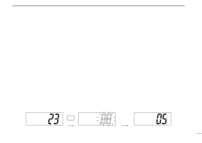
[Example]: Starting a normal scan.


INT

Push


INT


BUSY

INT


25W


SCAN

25W


25W


TAG

DUP

TAG


TAG

DUP


TAG

DUP


INTL


Normal scan


Normal scan


Scan starts.

When a signal is received


13

Image 17
Contents IM503 Channel 16 is automatically selected Mayday Mayday MaydayDS-100 #02 DSC Controller is required Table of Contents Page Priorities Operating RulesPrivacy Radio LicensesAdjusts the audio level. p Volume Control VOLPanel Description Panel descriptionPanel Description Function display Channel UP/DOWN Switches Y/Z PTT Switch PTTMicrophone Push and hold to transmit release to receive. pChannel selection Basic OperationChannel ÏCall channelRotate the channel selector to select a channel Basic OperationAtis and DSC channels FRG version only Receiving and transmitting Channel names Call channel programmingRotate the channel selector to select the desired channel Push Call to input and set the nameOptional voice scrambler operation Set mode Scrambler code itemActivating the scrambler Programming scrambler codesDescription DUALWATCH/TRI-WATCHOperation DUALWATCH/TRI-WATCH SimulationScan types Scan OperationsPriority Scan Normal ScanStarting a scan Setting tag channelsScan Operation Clearing all tag channels in the selected channel groupSET Mode Construction SET ModeSet mode programming Scan mode Set mode itemsScan resume timer Dual/tri watchLCD contrast Internal speakerScrambler code Scrambler typeIntercom operation Intercom OperationFuse replacement Connections and MaintenanceCleaning UnpackingConnections Connections and MaintenanceMicrophone hanger Overhead Mounting Mounting on Dashboard Using the supplied mounting bracketMounting the transceiver Using the optional mounting bracket Opening the transceiver case Optional unit installation145.0 5 23⁄32˝ Dimensions109.4 110.0 4 11⁄32˝ 165.0 6 1⁄2˝ 31.4 53.0 Unit mm inchProblem Possible Cause Solution TroubleshootingInternational channels Channel ListOptions Specifications and OptionsSpecifications PTT Switch PTT pgs Power Switch PWR pgsChannel 16/CALL Channel Switch 16C HM-134 REMOTE-CONTROL MicrophoneHM-134 REMOTE-CONTROL Microphone KEY Lock Indicator p Channel Group Indicator pgs12HM-134 REMOTE-CONTROL Microphone 1EXTERNAL Speaker Jack7WAIT Indicator S.A. and International channels Call channelA. channels International channelsPush H/L to select the output power, if necessary Display backlighting Lock functionsMonitor function Activating the lock functionTo turn the scrambler func Tion OFF, repeat step w Programming scramble codesPush Y/Z to select the desired channel Push Dual to start dualwatch or tri-watch To cancel dualwatch/tri-watch, push Dial againDualwatch/Tri- watch operation Transceiver’s functions Entering set modeMicrophone’s own functions Beep tone BeepAvailable characters Intercom beep functionHM-134 supplied accessories HM-134 Connections and InstallationInstallation Accessories included with the HM-134 Qty13HM-134 Connections and Installation 24 to 27 d mm 15⁄16 to 11⁄16˝ HM-134 Connections and InstallationMm 3⁄ 32˝ x Cut here MB-75 Template149 57⁄8˝ R11 Mm 3⁄32˝Installation notes Installation Notes0560 GER FRA ESP Intended Country of UseAUT NED POR DEN GBR BEL ITA FIN IRL LUX GRE SUI Kamiminami, Hirano-ku, Osaka 547-0003 JapanFrequency MHz Transmit Receive 01A