22
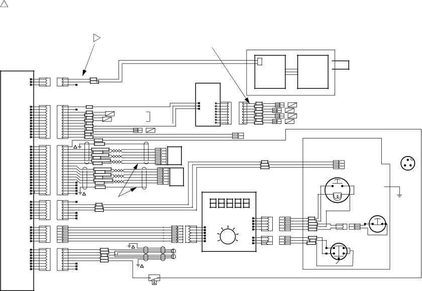
1Under operating conditions, voltage at J6 will be approximately 12 Vdc.
|
|
| 1 |
|
|
| 27 |
|
|
|
|
|
|
|
|
| |
|
|
|
|
|
|
|
| POWER SUPPLY ASSEMBLY 245223 |
|
|
|
|
|
| |||
|
|
|
|
|
|
|
|
|
|
|
|
|
|
|
| ||
|
|
|
|
|
|
|
|
|
| POWER |
|
|
| AIR INPUT |
|
|
|
|
|
|
|
|
|
|
|
|
| SUPPLY | POWER |
|
|
|
|
| |
|
|
|
|
|
|
|
|
|
|
|
|
|
|
|
| ||
|
|
|
|
|
|
|
|
|
| BARRIER | SUPPLY |
|
|
|
|
|
|
|
|
|
|
|
|
|
|
|
|
|
|
|
|
|
|
| |
| J6 |
|
|
|
|
|
|
|
| BOARD |
|
|
|
|
|
|
|
|
|
|
|
|
|
|
|
| 239790 |
|
|
|
|
|
|
| |
| 1 | 1 | 15VDC |
|
|
|
|
|
|
|
|
|
|
|
|
| |
|
|
|
|
|
|
|
|
|
|
|
|
|
|
| |||
| 2 | 2 | RED |
|
|
|
|
|
|
|
|
|
|
|
|
|
|
| COM |
|
|
|
|
|
|
|
|
|
|
|
|
|
| ||
| 3 | 3 | BLACK |
|
|
|
|
|
|
|
|
|
|
|
|
|
|
|
|
|
|
|
|
|
|
|
|
|
|
|
|
|
| ||
|
|
|
|
|
|
| SOLENOID |
|
|
|
|
|
|
|
|
| |
MAIN CONTROL |
| JUMPER (15V) |
|
|
|
| BOARD |
|
|
|
|
|
|
|
|
|
|
BOARD |
|
|
|
|
|
| 246899 | P4 | 1 |
|
|
|
|
|
|
|
|
| J5 |
|
|
|
|
| P | 1 | + |
|
|
|
|
|
|
| |
248349 |
| 12VDC |
|
|
| 2 | RED | MOTOR B DOWN |
|
|
|
|
|
| |||
1 | 1 |
|
|
| S | 2 | - |
|
|
|
|
|
| ||||
| RED |
|
|
| 3 | BLACK |
|
|
|
|
|
|
| ||||
| 2 | 2 |
|
|
| G | 3 | + |
|
|
|
|
|
|
| ||
|
|
|
|
|
|
|
|
|
|
|
| ||||||
|
| + |
|
| 4 | RED | MOTOR B UP |
|
|
|
|
|
| ||||
| 3 | 3 |
|
|
|
| 4 | - |
|
|
|
|
|
| |||
| 4 | 4 | RED | - | SOLENOID VALVE A |
|
| 5 | BLACK |
|
|
|
|
|
|
| |
| BLACK | FLUID |
| 5 | + |
|
|
|
|
|
|
| |||||
|
|
|
|
|
| 6 | RED | MOTOR A DOWN |
|
|
|
|
|
| |||
| 5 | 5 |
| + |
|
| 6 | - |
|
|
|
|
|
| |||
| 6 | 6 | RED | - | SOLENOID VALVE B | VALVES |
| 7 | BLACK |
|
|
|
|
|
|
| |
| BLACK |
| 7 | + |
|
|
|
|
|
|
| ||||||
| 7 | 7 |
|
|
|
| 8 | RED | MOTOR A UP |
|
|
|
|
|
| ||
|
|
|
|
|
| 8 | - |
|
|
|
|
|
| ||||
| 8 | 8 | ORANGE |
|
|
|
|
| BLACK |
|
|
|
|
|
|
| |
| BLACK |
|
|
|
|
|
| 15D794 |
|
|
|
|
|
|
| ||
| 9 | 9 | + |
|
|
|
|
|
|
|
|
|
|
|
|
|
|
| 10 | 10 | RED | CABLE # 114213 | OPT. SOLENOID, RECIRC. 552180 | ALARM ASSY | 15A849 |
|
|
|
|
|
|
|
| ||
| - |
|
|
|
|
|
|
|
| ||||||||
| 11 | 11 | BLACK |
|
|
|
|
|
|
|
|
|
|
|
|
|
|
| RED |
|
|
|
|
| ALARM + |
| FRONT PANEL |
|
|
|
| ||||
| 12 | 12 |
|
|
|
|
|
|
|
|
|
| |||||
| BLACK |
|
|
|
|
| ALARM COM |
|
|
|
|
|
|
| |||
|
|
|
|
|
|
|
|
|
|
|
|
|
|
| |||
|
|
| BLACK |
|
|
|
|
|
|
|
|
|
|
|
|
|
|
| J4 |
| 12VDC |
|
|
|
|
|
|
|
|
|
|
|
|
|
|
| 1 | SHIELD |
|
|
|
|
|
|
|
|
|
|
|
|
|
| |
| 1 | 1 |
|
|
|
|
|
|
|
|
|
|
|
| COM PORT PIN LOCATIONS |
| |
| 2 | 2 |
|
| 5 |
|
|
|
|
|
|
|
|
|
|
| |
| WHITE_W/GRN |
| SENSOR |
|
|
|
|
|
|
|
| FRONT SIDE VIEW |
| ||||
| 3 | 3 |
| 2 |
|
|
|
| COM PORT |
|
|
|
| ||||
| GREEN |
|
| 243678 |
|
|
|
|
|
|
|
|
| ||||
| 4 | 4 | WHITE_W/ORANGE |
| 4 |
|
|
|
| RS232 |
|
| (OPPOSITE SIDE OF SOLDER CUPS) |
| |||
| 5 | 5 |
| 1 |
|
|
|
|
|
|
|
|
|
| |||
| ORANGE |
|
| "A" |
|
|
|
| CONNECTOR |
|
|
|
| ||||
| 6 | 6 |
|
| 6 |
|
|
|
|
|
|
|
| ||||
| WHITE_W/BLUE |
|
|
|
|
| 1 |
|
|
| 1 |
| |||||
| 7 | 7 |
| 3 |
|
| RED |
| TX |
|
|
| |||||
| BLUE |
|
|
|
|
|
| 2 |
|
|
|
| |||||
| 8 | 8 | CABLE # 15D607 (X2) |
|
|
|
| WHITE |
| RX |
|
|
|
| |||
|
|
|
|
|
|
| 3 |
|
|
|
| ||||||
| 9 | 9 |
| 5 |
|
|
| BLACK |
| GND |
|
| 2 | 3 | |||
|
|
|
|
|
|
|
|
|
|
| |||||||
| 10 | 10 | WHITE_W/GRN |
| 2 | SENSOR |
|
| COMM PORT ASSY |
|
|
|
|
|
|
| |
| GREEN |
|
|
|
|
|
|
|
|
|
|
| |||||
| 11 | 11 |
|
| 4 |
|
|
|
|
|
|
|
|
|
| ||
| WHITE_W/ORANGE |
| 243678 |
|
| 15A850 |
| START |
|
|
|
|
| ||||
| 12 | 12 |
| 1 |
|
|
|
|
|
|
|
| |||||
| ORANGE |
|
|
|
|
|
|
|
|
|
|
| |||||
| 13 | 13 |
| 6 | "B" |
|
|
|
|
|
|
|
|
|
| ||
| WHITE_W/BLUE |
|
|
|
|
|
|
|
|
|
|
| |||||
| 14 | 14 |
| 3 |
|
|
|
|
|
|
|
|
|
| |||
| 15 | 15 | BLUE |
|
|
|
|
|
|
|
| 3 | 4 |
|
|
|
|
|
|
|
|
|
|
|
|
|
|
|
|
|
| ||||
| 16 | 16 | SHIELD |
|
|
|
|
|
|
|
|
|
|
|
|
| |
| 17 | 17 |
|
|
|
|
|
|
|
|
|
|
|
|
|
|
|
| 18 | 18 | 1 |
|
|
|
|
|
|
|
| B | A |
|
|
|
|
|
|
|
| 26 |
|
|
|
|
|
|
|
|
|
|
|
| |
| J2 |
|
|
|
|
|
|
|
|
|
|
| GND |
|
|
| |
| 1 | 1 |
|
|
|
|
|
|
|
|
|
|
|
|
|
| |
|
|
|
|
|
|
|
|
|
|
|
|
|
|
|
| ||
| 2 | 2 | RED |
|
|
|
|
|
|
|
|
|
|
|
| START/STOP |
|
| 3 | 3 |
|
|
|
|
|
|
|
| LIGHT |
|
|
| SWITCH ASSY | ||
| WHITE |
|
|
|
|
|
|
|
|
|
|
| |||||
| 4 | 4 | BLACK |
|
|
|
|
|
|
|
|
|
|
|
| 15A851 |
|
| 5 | 5 |
|
|
|
|
|
|
|
|
|
|
|
|
| ||
|
|
|
|
|
|
|
|
|
|
|
|
| STOP |
| |||
| 6 | 6 |
|
|
|
|
|
|
| J2 |
|
|
|
|
|
| |
|
|
|
|
|
|
|
|
|
|
|
|
|
|
| |||
| 7 | 7 |
|
|
|
|
| DISPLAY BOARD |
| 1 | 1 |
|
|
|
|
|
|
|
|
|
|
|
|
|
|
|
| RED |
|
|
|
|
|
| |
|
|
|
|
|
|
|
|
| 2 | 2 |
|
| 1 | 2 |
|
| |
|
|
|
|
|
|
|
| 245706 |
| 3 | WHITE |
|
|
|
| ||
| J1 |
| CABLE # 15A854 (MAIN TO DISPLAY) |
| J1 |
| 3 | 1 |
|
|
|
|
| ||||
|
|
|
|
|
| BROWN |
| 1 |
|
|
| ||||||
| 1 |
| 1 |
|
| 1 | 1 |
|
| 4 | 4 | 2 |
|
|
|
| |
|
|
|
|
|
|
| GREEN |
| 2 |
|
|
| |||||
| 2 |
| 2 |
|
| 2 | 2 |
|
| 5 | 5 |
|
|
|
|
| |
|
|
|
|
|
|
| BLACK |
|
|
|
|
|
| ||||
| 3 |
| 3 |
|
| 3 | 3 |
|
| J3 |
|
|
|
|
|
|
|
| 4 |
| 4 |
|
| 4 | 4 |
|
|
|
|
|
|
|
|
| |
|
|
|
|
|
| 1 | 1 |
|
|
|
|
|
| ||||
| 5 |
| 5 |
|
| 5 | 5 |
|
|
|
|
| GND | KEY SWITCH ASSY |
| ||
|
|
|
|
|
|
|
|
|
| 2 | BLACK |
|
|
|
|
| |
| 6 |
| 6 |
|
| 6 | 6 |
|
| 2 |
|
|
|
| 15A852 |
| |
|
|
|
|
|
| 3 | RED |
|
|
|
|
| |||||
|
|
|
|
|
|
|
|
|
| 3 |
|
|
|
|
|
| |
|
|
|
|
|
|
|
|
|
|
| GREEN |
|
|
|
|
|
|
| J8 |
| SIGNAL A |
| 1 |
|
|
|
|
|
| 2 | 1 |
|
|
|
|
| 1 | 1 | WHITE |
|
|
|
|
|
|
|
|
|
|
|
|
| |
| 2 | 2 | COM |
|
| METER A |
|
|
|
|
|
|
|
|
|
| |
| BLACK |
| 234628 |
|
|
|
|
|
| KEY SWITCH |
|
|
| ||||
| 3 | 3 | 12VDC |
|
|
|
|
|
|
|
|
|
|
| |||
| RED |
|
|
|
|
|
| 7 |
|
|
|
| |||||
| 4 | 4 | SIGNAL B |
|
| METER B |
|
|
|
| 8 | MOM. |
|
|
| ||
| WHITE |
|
|
|
|
|
|
|
|
|
| ||||||
| 5 | 5 |
|
|
|
|
|
|
|
|
|
|
|
|
|
| |
|
| ORANGE |
|
|
|
|
|
|
| + | - |
|
|
|
| ||
| 6 | 6 |
|
|
|
|
|
|
|
|
|
|
|
| |||
|
|
|
|
|
|
|
|
|
|
|
|
|
| ||||
| 7 | 7 |
|
|
| 1 |
|
|
|
|
|
|
|
|
|
|
|
| 8 | 8 |
|
|
|
|
|
|
|
|
|
|
|
|
|
| |
|
|
|
|
|
|
|
|
|
|
|
|
|
|
|
| ||
|
|
|
|
|
| AIR FLOW SWITCH |
|
|
|
|
|
|
|
|
|
|
|
|
|
|
|
|
| 119159 |
|
|
|
|
|
|
|
|
|
|
|
Electrical | Electrical Schematic |
Schematic |
|
309909H