Invacare 1098330, 60106X144, 1101100, 1098348, 1098318, 1097049 Functional Reach From a Wheelchair

Page 10

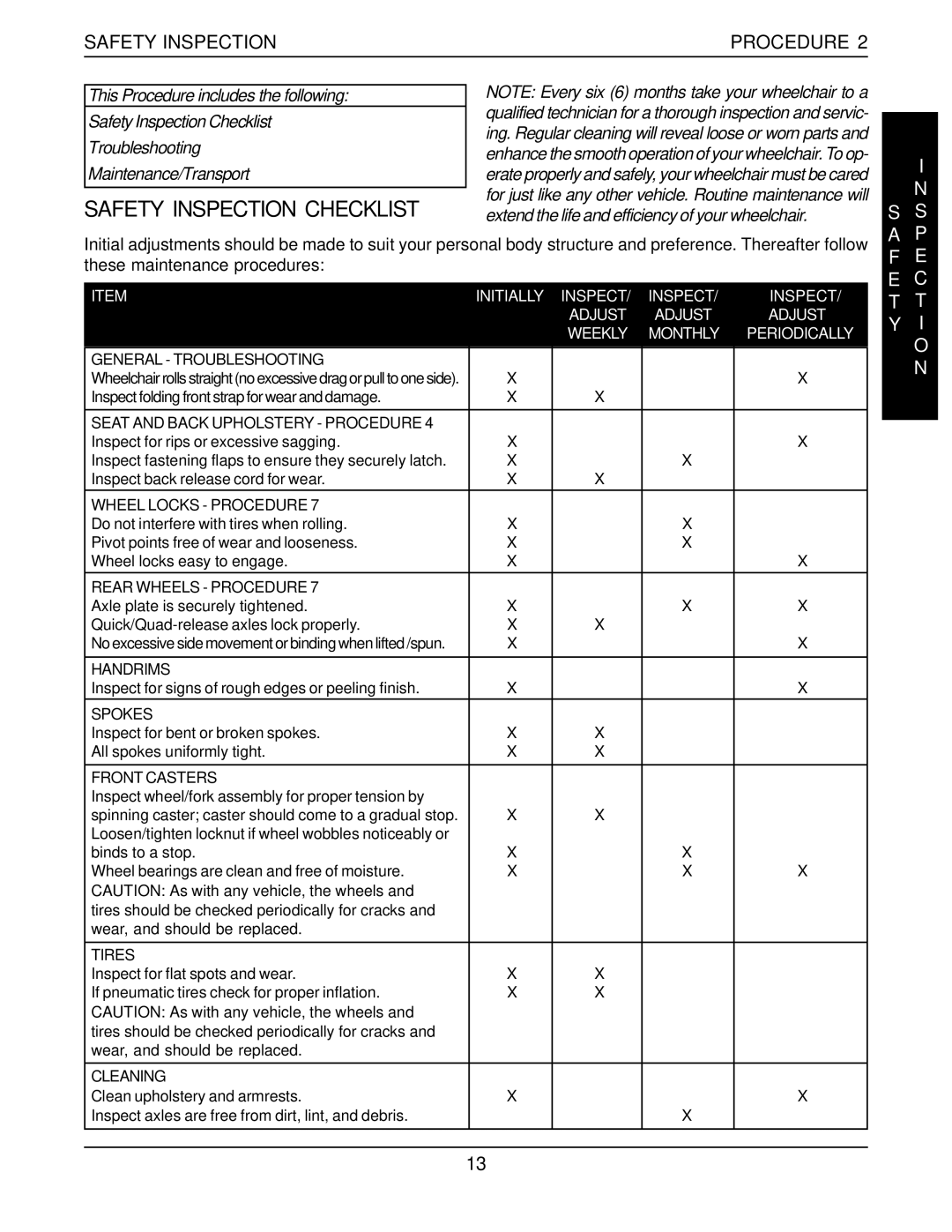
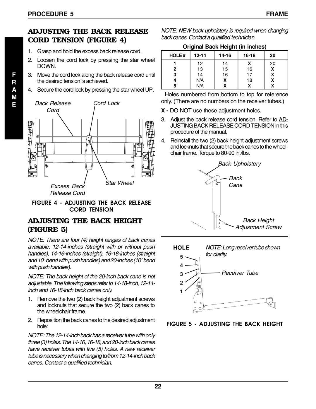
PROCEDURE 1

GENERAL GUIDELINES

G

U G I E D N E E L R I A N L E

S

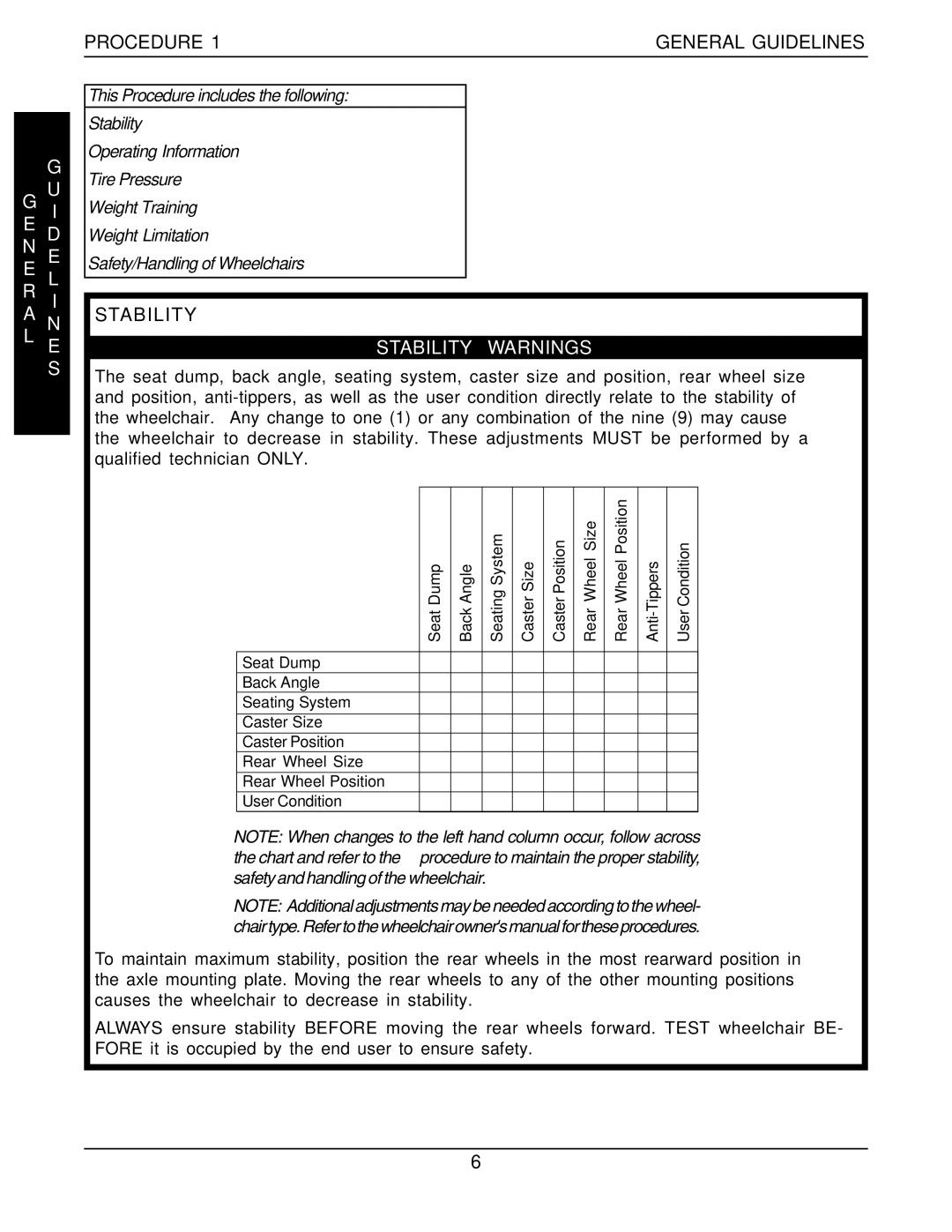
Many activities require the wheelchair user to reach, bend and transfer in and out of the wheelchair. These movements will cause a change to the normal bal- ance, the center of gravity, and the weight distribu- tion of the wheelchair. To determine and establish your particular safety limits, practice bending, reach- ing and transferring activities in several combina- tions in the presence of a qualified healthcare pro- fessional BEFORE attempting active use of the wheelchair.

Proper positioning is essential for your safety. When reaching, leaning, or bending forward, it is important to use the front casters as a tool to maintain stability and balance.

LENGTHENING THE WHEELBASE will increase the stability and maintain standard maneuverability of the wheelchair.

SHORTENING THE WHEELBASE will increase the maneuverability and distribute additional weight onto the rear wheels.


72


FORWARD REACH


(ADULTS)


64


COMFORTABLE

MAXIMUM

61


56


53


48

INCHES


42


40


32


29


25


16


8


0

8

16

24

37

40

48

0


INCHES

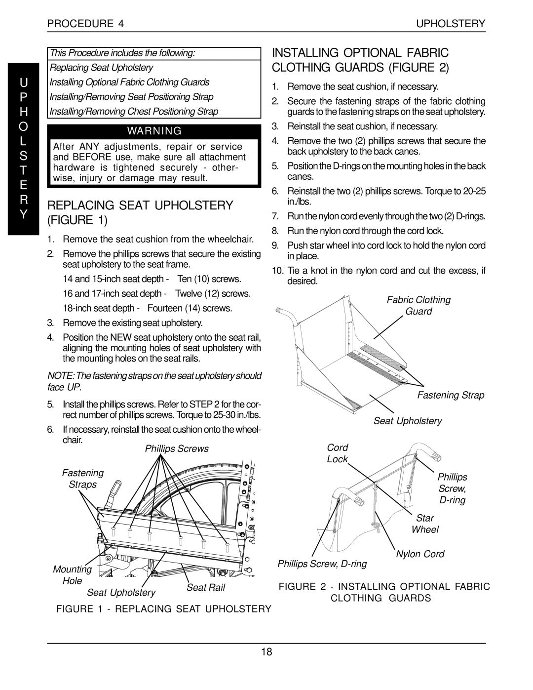
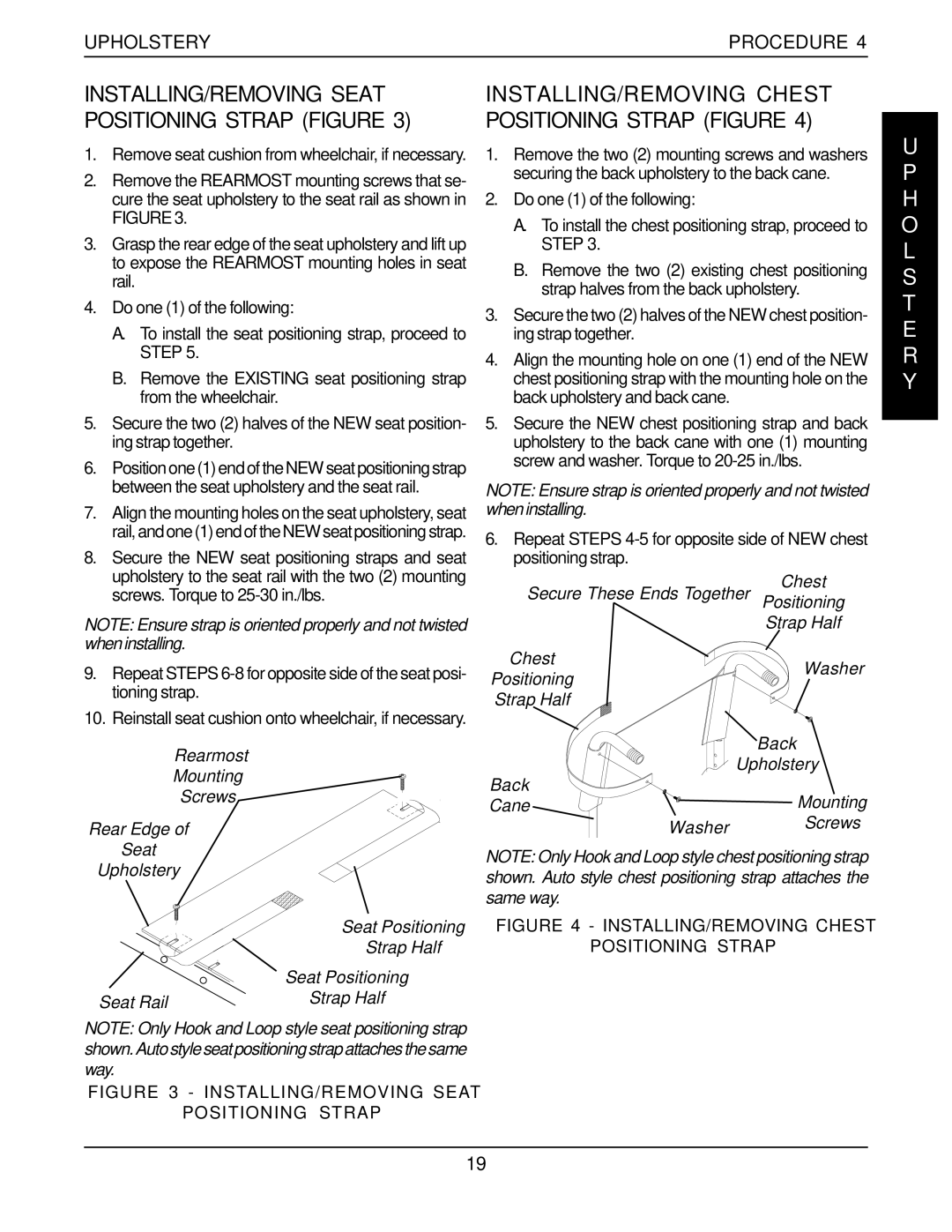
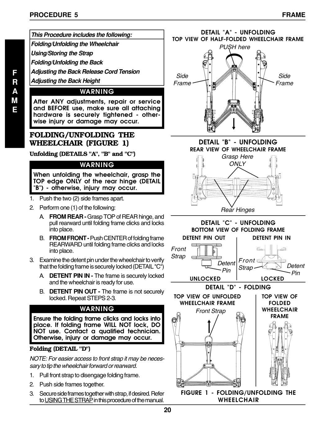
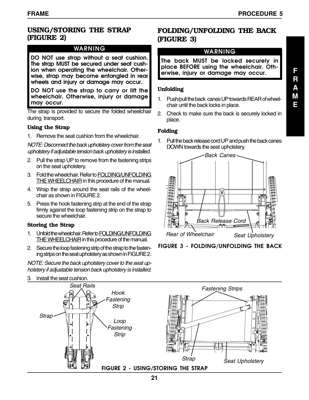
REACHING, LEANING AND BENDING - FORWARD.

Position the front casters so that they are extended as far forward as possible and engage wheel locks.

WARNING

DO NOT attempt to reach objects if you have to move forward in the seat or pick them up from the floor by reaching down between your knees.

Example 46% 54%

103 lbs. 130 lbs.

UNOCCUPIED

OCCUPIED

SHORTENING

Rear of

THE

Wheelchair

WHEELBASE

LENGTHENING


THE

Axle Mounting

WHEELBASE


Plate


Functional Reach From a Wheelchair

The approximate reach-limit values shown in the accom- panying graph were derived on the basis of a sample of 91 male and 36 female wheelchair users. Note the differ- ence between the maximum and the comfortable reach limits, a subjective but important consideration in design.

10

Image 10
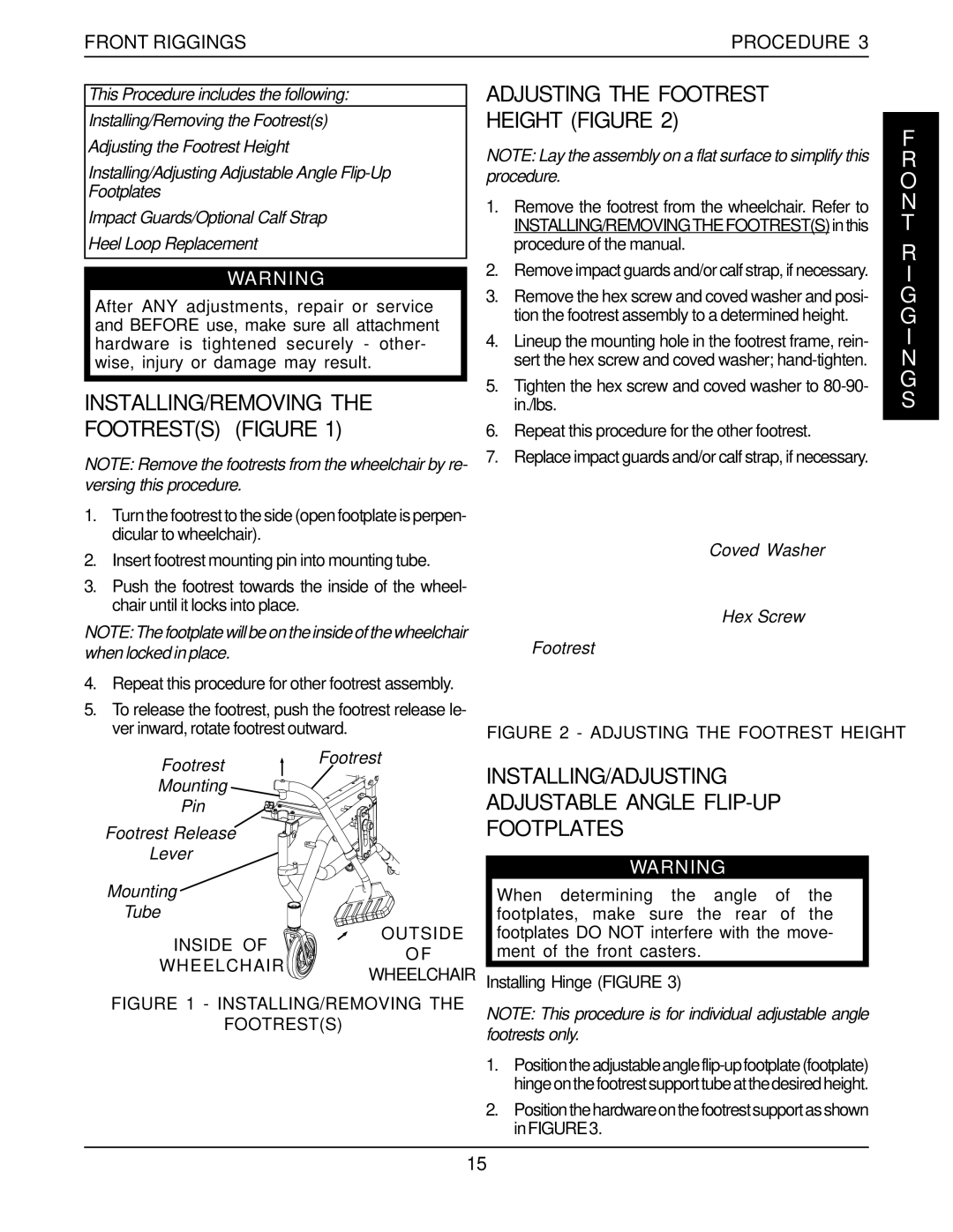
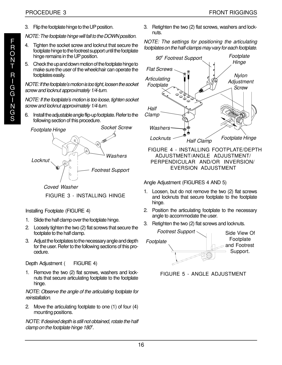
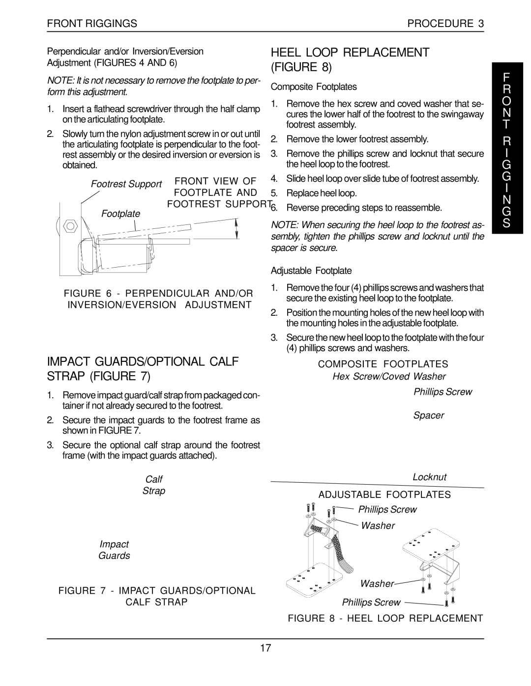
Contents 52,-4c R N I N G E C I a L T E STable of Contents B E L S LabelsSpecifications SpyderProcedure General Guidelines I E D N E E L R I a N L EGeneral Guidelines Procedure N L EI E D RE L I a N Tire PressureStability And Balance SAFETY/HANDLING WheelchairsCoping With Everyday Obstacles Functional Reach From a Wheelchair Tilting StairwaysESCALATORS? Sorry Transferring To And From Other SeatsSafety Inspection Checklist Safety Inspection ProcedureMAINTENANCE/TRANSPORTING TroubleshootingProcedure 2SAFETY Inspection INSTALLING/ADJUSTING Adjustable Angle FLIP-UP Footplates INSTALLING/REMOVING the Footrests FigureAdjusting the Footrest Height Figure Front Riggings ProcedureDepth Adjustment Figure Procedure Front RiggingsInstalling Footplate Figure Angle Adjustment Figures 4Impact GUARDS/OPTIONAL Calf Strap Figure Heel Loop Replacement FigureAdjustable Footplate Composite FootplatesH O L S T E R Y Installing Optional Fabric Clothing Guards FigureReplacing Seat Upholstery Figure Upholstery Procedure FOLDING/UNFOLDING the Wheelchair Figure Procedure FrameM E Unfolding Details A, B and CFrame Procedure USING/STORING the Strap FigureFOLDING/UNFOLDING the Back Figure M E Adjusting the Back Release Cord Tension FigureAdjusting the Back Height Figure Back Release Cord LockAdjusting the T-ARMS Adjusting Half ARM Height FigureINSTALLING/REMOVING T-ARMS Figure Arms ProcedureInside T-Arm Procedure ArmsFollowing Set Screws Outside Post Arm Release Lever Arm PadArm Side Guard Adjusting T-ARM Transfer Assists AND/OR Side Guards FigureInstalling Optional Rigid Clothing Guards Figure Socket Screws Transfer Assist Bottom ClampProcedure Rear Wheels REMOVING/INSTALLING Rear Wheels FigureAdjusting QUICK-RELEASE Axles Figure A RRear Wheels Procedure Installing QUAD-RELEASE Axles FigureAdjusting QUAD-RELEASE Handles And/or Out FigureReplacing the High/Undermount Wheel Lock REPLACING/ADJUSTING the Wheel Lock FigureAdjusting the High/Undermount Wheel Lock Hex Screws High Mount Wheel LockInstalling Anti-tippers Figure INSTALLING/ADJUSTINGAdjusting Anti-tippers Figure ANTI-TIPPERSPage Warranty Limited WarrantyR R a N T Y One InvacareWay