![]() RANGER® 305LPG
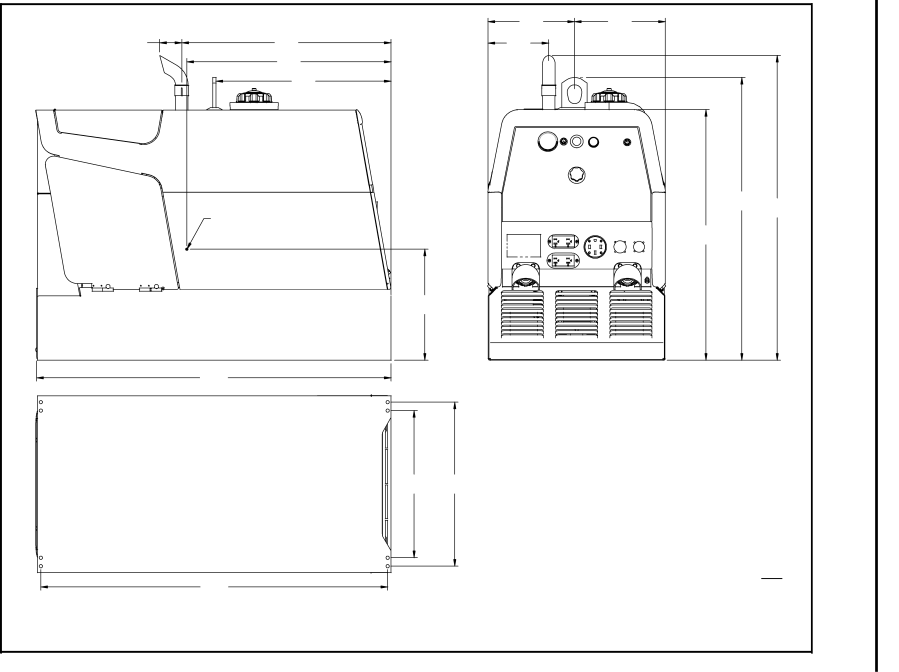
RANGER® 305LPG
|
| 10.28 | 10.78 |
| F- |
|
|
| 12 | ||
|
| 261.0 | 273.9 |
| |
2.62 | 24.86 | 7.22 |
|
| |
|
|
| |||
66.5 | 631.3 | 183.3 |
|
|
|
| 23.50 |
|
|
|
|
| 596.9 |
|
|
|
|
| 20.80 |
|
|
|
|
| 528.3 |
|
|
|
|
|
|
| 33.62 | 36.24 |
|
|
|
| 854.0 |
| |
| CENTER OF GRAVITY |
|
| 920.4 |
|
|
|
|
|
| |
|
|
| 29.80 |
|
|
|
| CIRCUIT | 756.9 |
| DIMENSION |
|
| BREAKERS |
|
| |
| 16.75 |
|
|
| |
| 425.4 |
|
|
| |
|
|
|
|
| |
| 42.10 |
|
|
| |
| 1069.5 |
|
|
| |
|
|
|
|
| |
| 17.50 | 19.50 |
|
|
|
| 444.5 | 495.3 |
|
|
|
| 41.20 |
|
| INCH |
|
|
|
| MM |
| |
| 1046.5 |
|
|
|
|
TRUCK/UNDERCARRIAGE MOUNTING HOLES |
|
|
|
| |
|
|
|
| A.01 | F |
|
|
|
| ||
|
|
|
| M22449 | |