


|
|
| LEARNING TO WELD | |
|
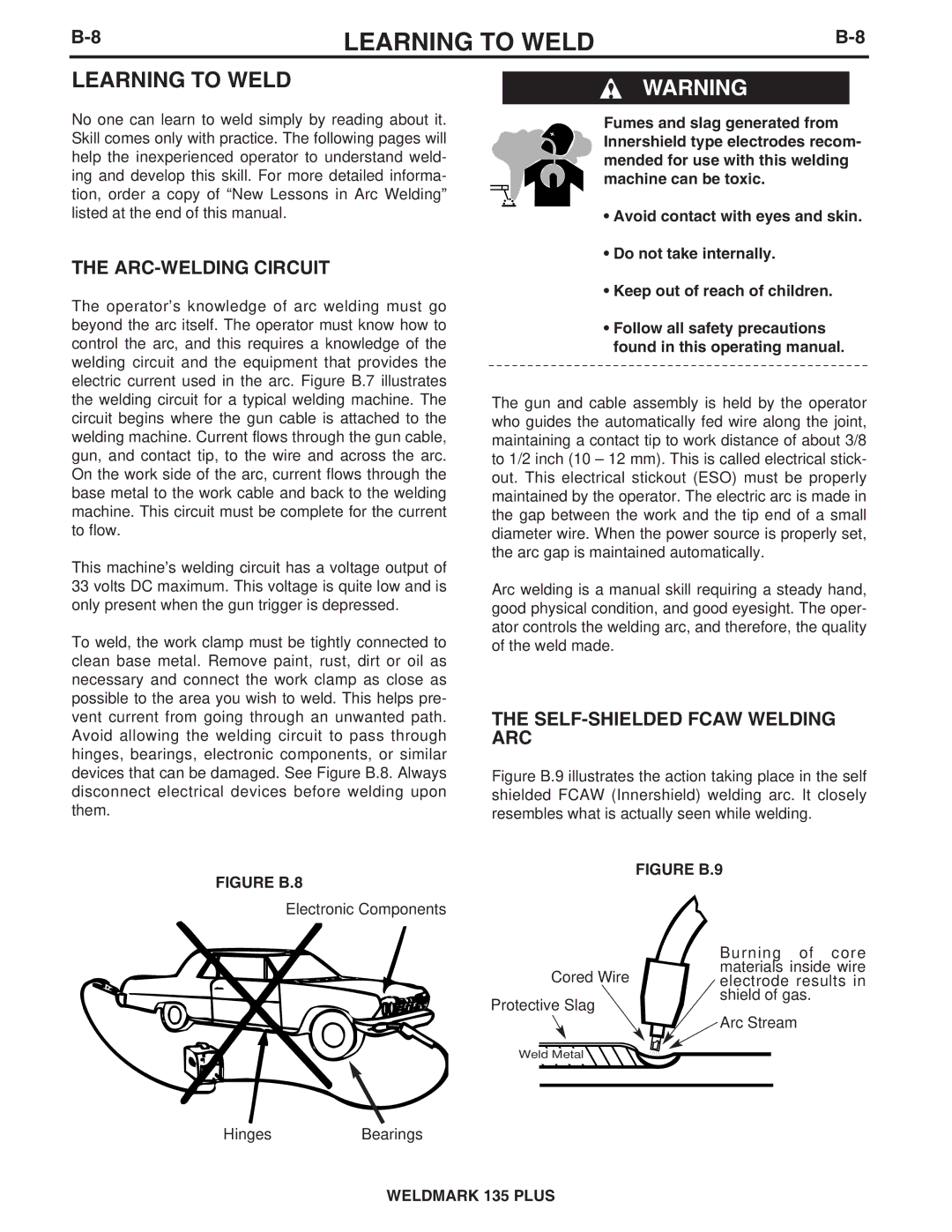
MACHINE SET UP FOR THE GMAW (MIG) PROCESS
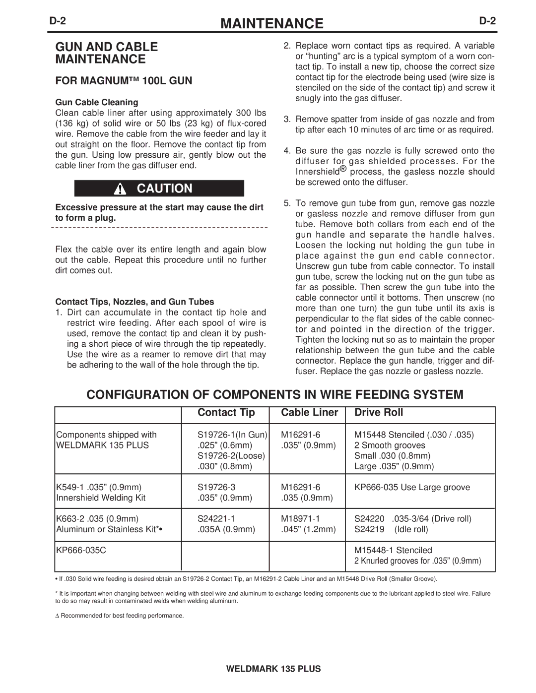
1.See PROCESS GUIDELINES in the OPERATION section for selection of welding wire and shielding gas, and for range of metal thicknesses that can be welded.
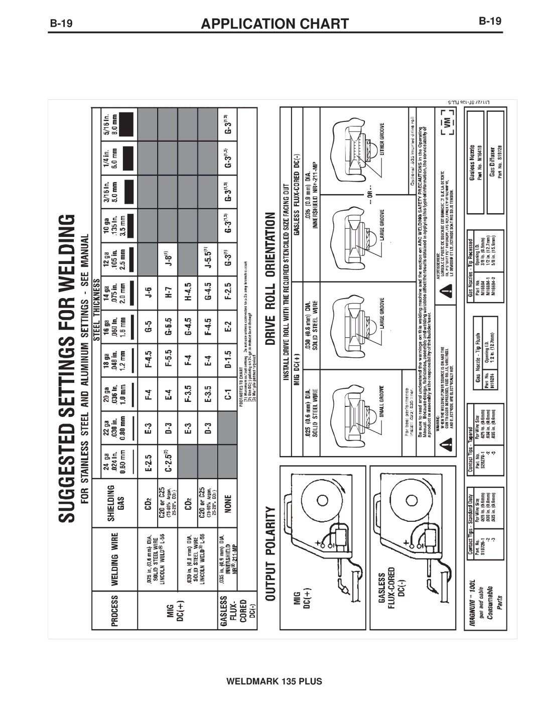
2.See the Application Guide on the inside of wire feed section door for information on setting the controls.
3.Set the “Voltage” and “Wire Speed” controls to the settings suggested on the Application Guide for the welding wire and base metal thickness being used. The voltage control is marked “V” and the wire feed speed is marked ‘’olo.’’
4.Check that the polarity is correct for the welding wire being used. Set the polarity for DC(+) when welding with the GMAW (MIG) process. See Work Cable Installation in the INSTALLATION section for instructions for changing polarity.
5.Check that the gas nozzle and proper size liner and contact tip are being used and that the gas supply is turned on. If adjustable, set for 15 to 20 cubic feet per hour (7 to 10 l/min.) under normal conditions, increase to as high as 35 CFH (17 I/min.) under drafty (slightly windy) conditions.
6.Connect work clamp to metal to be welded. Work clamp must make good electrical contact to the work piece. The work piece must also be grounded as stated in the “Arc Welding Safety Precautions” at the beginning of this manual.
WELDING TECHNIQUES FOR THE GMAW (MIG) PROCESS
Four simple manipulations are of prime importance when welding. With complete mastery of the four, welding will be easy. They are as follows:
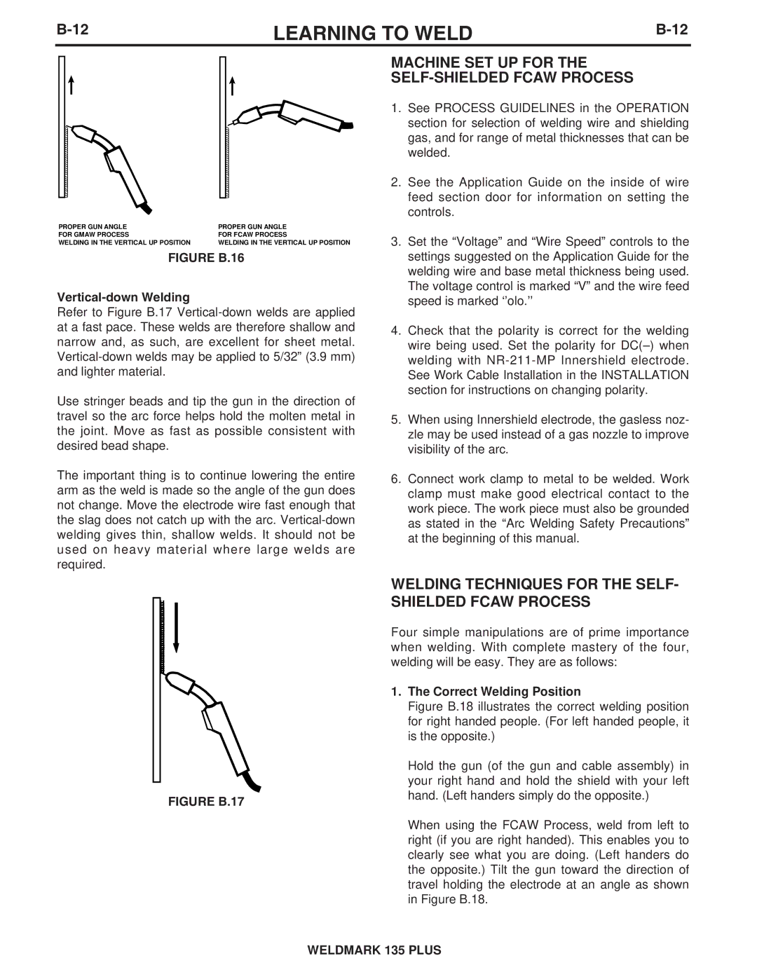
1.The Correct Welding Position
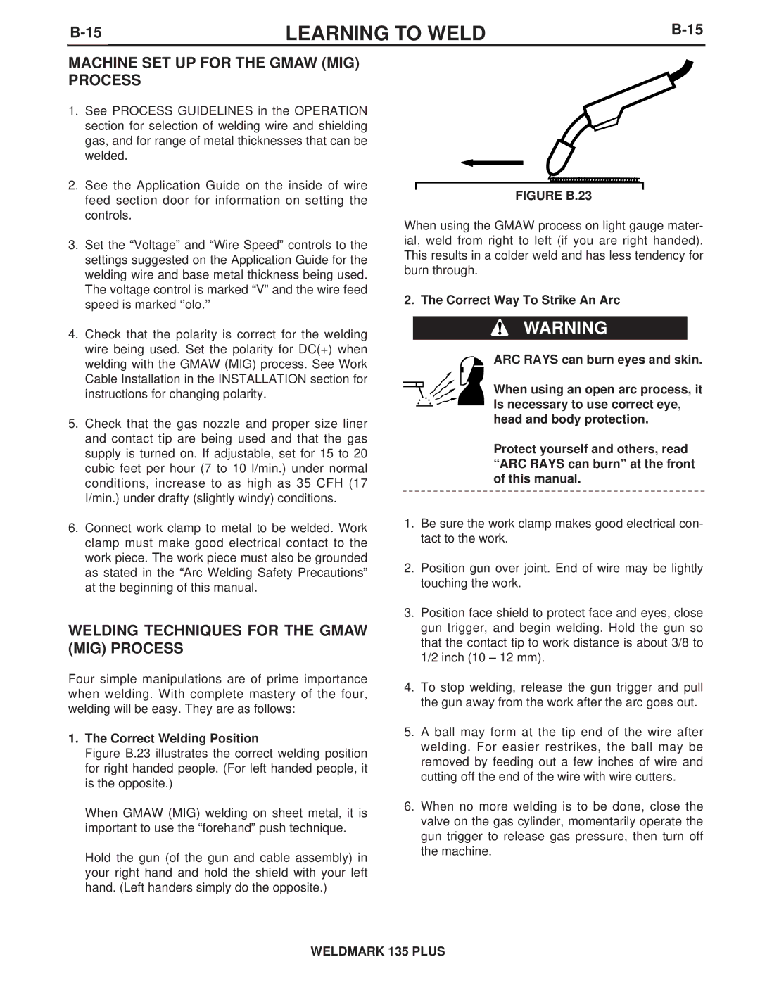
Figure B.23 illustrates the correct welding position for right handed people. (For left handed people, it is the opposite.)
When GMAW (MIG) welding on sheet metal, it is important to use the “forehand” push technique.
Hold the gun (of the gun and cable assembly) in your right hand and hold the shield with your left hand. (Left handers simply do the opposite.)
FIGURE B.23
When using the GMAW process on light gauge mater- ial, weld from right to left (if you are right handed). This results in a colder weld and has less tendency for burn through.
2. The Correct Way To Strike An Arc
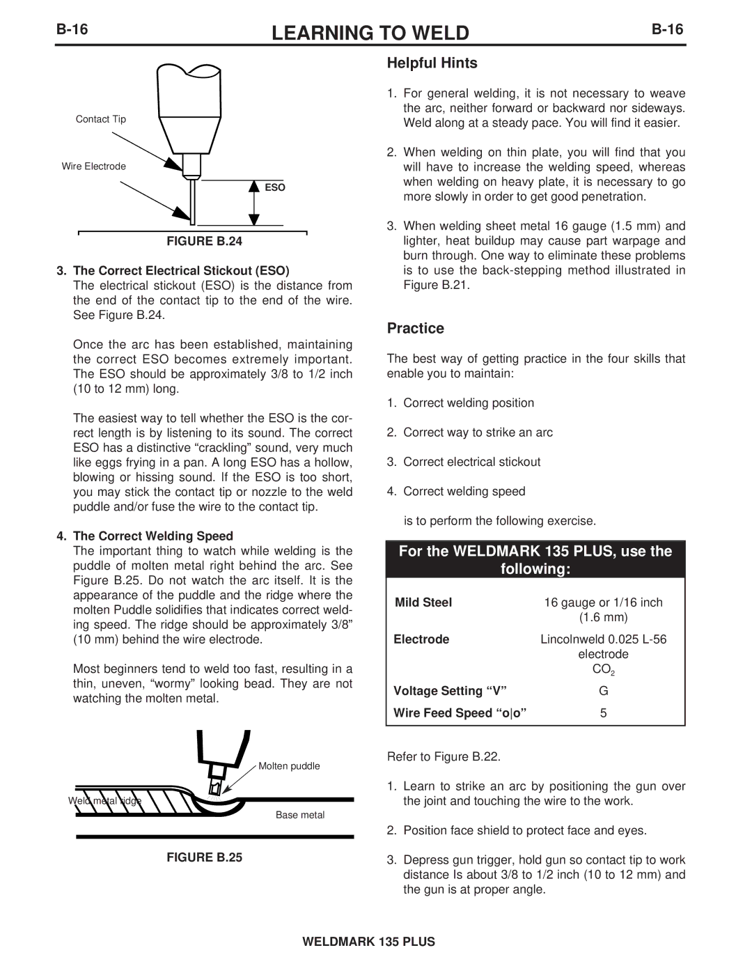
WARNING
ARC RAYS can burn eyes and skin.
When using an open arc process, it Is necessary to use correct eye, head and body protection.
Protect yourself and others, read “ARC RAYS can burn” at the front of this manual.
1.Be sure the work clamp makes good electrical con- tact to the work.
2.Position gun over joint. End of wire may be lightly touching the work.
3.Position face shield to protect face and eyes, close gun trigger, and begin welding. Hold the gun so that the contact tip to work distance is about 3/8 to 1/2 inch (10 – 12 mm).
4.To stop welding, release the gun trigger and pull the gun away from the work after the arc goes out.
5.A ball may form at the tip end of the wire after welding. For easier restrikes, the ball may be removed by feeding out a few inches of wire and cutting off the end of the wire with wire cutters.
6.When no more welding is to be done, close the valve on the gas cylinder, momentarily operate the gun trigger to release gas pressure, then turn off the machine.
WELDMARK 135 PLUS